BC108 Transistor: Difference between revisions
From DT Online
m (Added image) |
m (Added Amazon Link) |
||
| (5 intermediate revisions by the same user not shown) | |||
| Line 1: | Line 1: | ||
<div class="floatright"><dtamazon type="search" search="BC108 Transistor"><img alt="BC108.png" src="/images/c/c2/BC108.png" width="250" height="148" /></a></dtamazon></div> | |||
__TOC__ | |||
The input is connected to the Base via a limiting resistor (typically 1K). The Emitter is connected to the negative (-ve) supply (0V). | =====Description===== | ||
A '''BC108''' Transistor is an '''NPN''' ''(Negative-Positive-Negative)'' [https://en.wikipedia.org/wiki/Bipolar_junction_transistor#NPN '''Bipolar Transistor''']: the most commonly used transistor configuration | |||
The [https://en.wikipedia.org/wiki/BC548 '''BC108'''] Collector is connected to the positive ''(+ve)'' supply via the load. NB: If the load is inductive i.e. has coil windings such as a relay, solenoid or motor, then it is usual to connect a diode across it to prevent the Back EMF from damaging the transistor. ''(Cathode to supply)''. | |||
=====Features and Applications===== | |||
The input is connected to the Base via a limiting resistor ''(typically 1K)''. The Emitter is connected to the negative ''(-ve)'' supply ''(0V)''. | |||
| Line 13: | Line 23: | ||
* bCurrent handling capacity 300 mAmps max. | * bCurrent handling capacity 300 mAmps max. | ||
* Amplification (gain) greater than 125. | * Amplification (gain) greater than 125. | ||
=====Dual Transistor Switch (Darlington Pair)===== | |||
[[File: DualTransistorSwitch.png|200px|right]] | |||
The switching action of transistors is improved by combining them in a [https://en.wikipedia.org/wiki/Darlington_transistor '''Darlington Pair'''] configuration. | |||
The "first" transistor acts as a signal amplifier which triggers the "second" transistor ''(e.g. '''[[BFY51 Transistor|BFY51]]''')'' with a larger signal than the original input and thus improves its switching action. A base voltage of 1.2V is required to trigger the "pair". | |||
The purpose of the '''IN4001 [[Diode]]''' shown is to restrict any [https://en.wikipedia.org/wiki/Counter-electromotive_force '''Back EMF'''] resulting from the Transistor being used to switch an inductive device ''(e.g. '''[[Electric Motor]]''', '''[[Solenoid]]''' or '''[[Relays|Relay]]'''). | |||
---- | |||
<span style="color: green">'''Note:'''</span> | |||
* <span style="color: green">When choosing a transistor it is important to make sure that the gain is high enough for the required use and that the maximum current which it can handle is sufficient to drive the output device. e.g. BFY 51 gain > 40 , max Ic = 1 amp.</span> | |||
* <span style="color: green">If the max Ic value is exceeded, the transistor will probably "burn out".</span> | |||
* <span style="color: green">The transistor acts as a '''NOT''' gate ''(inverter)'' since a "high" at the base gives a "low" at the collector. ''(i.e. when the transistor switches on, the collector voltage decreases).''</span> | |||
---- | |||
{{Transistor & IC Buyers Guide}} | |||
[[Category:Secondary]] | [[Category:Secondary]] | ||
[[Category:Electronics | [[Category:Electronics Components]] | ||
Latest revision as of 15:00, 7 November 2017
Description
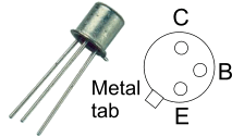
A BC108 Transistor is an NPN (Negative-Positive-Negative) Bipolar Transistor: the most commonly used transistor configuration
The BC108 Collector is connected to the positive (+ve) supply via the load. NB: If the load is inductive i.e. has coil windings such as a relay, solenoid or motor, then it is usual to connect a diode across it to prevent the Back EMF from damaging the transistor. (Cathode to supply).
Features and Applications
The input is connected to the Base via a limiting resistor (typically 1K). The Emitter is connected to the negative (-ve) supply (0V).
Uses: As current amplifiers and electronic switches, for example LED Drive Amplifiers, Relay Drive Amplifiers, Audio Amplifiers.
Data: Voltage between Collector and Emitter 3 - 20Volts max.
- Power handling capacity 100 mWatts max.
- bCurrent handling capacity 300 mAmps max.
- Amplification (gain) greater than 125.
Dual Transistor Switch (Darlington Pair)

The switching action of transistors is improved by combining them in a Darlington Pair configuration.
The "first" transistor acts as a signal amplifier which triggers the "second" transistor (e.g. BFY51) with a larger signal than the original input and thus improves its switching action. A base voltage of 1.2V is required to trigger the "pair".
The purpose of the IN4001 Diode shown is to restrict any Back EMF resulting from the Transistor being used to switch an inductive device (e.g. Electric Motor, Solenoid or Relay).
Note:
- When choosing a transistor it is important to make sure that the gain is high enough for the required use and that the maximum current which it can handle is sufficient to drive the output device. e.g. BFY 51 gain > 40 , max Ic = 1 amp.
- If the max Ic value is exceeded, the transistor will probably "burn out".
- The transistor acts as a NOT gate (inverter) since a "high" at the base gives a "low" at the collector. (i.e. when the transistor switches on, the collector voltage decreases).


