PCBdesigner.jpg: Difference between revisions
From DT Online
(Added link to PCB Designer) |
mNo edit summary |
||
| Line 1: | Line 1: | ||
[http://www.dtonline.org/apps/pcb/app?1&0&1&0&0&0&0 '''PCB Designer'''] - design simple electronics control circuits by first indentifying the '''Input''' - '''Process''' - '''Output'' required. | [http://www.dtonline.org/apps/pcb/app?1&0&1&0&0&0&0 '''PCB Designer'''] - design simple electronics control circuits by first indentifying the '''Input''' - '''Process''' - '''Output''' required. | ||
For each of these elements, and in any order, select the particular functions and components required - e.g. Light Sensor - Darlington Pair - LED | |||
A Schematic or circuit diagram can then be created and this can be viewed as a PCB Layout, a Silk Screen, or as images of the components in situ. | A Schematic or circuit diagram can then be created and this can be viewed as a PCB Layout, a Silk Screen, or as images of the components in situ. | ||
Latest revision as of 10:29, 4 June 2015
PCB Designer - design simple electronics control circuits by first indentifying the Input - Process - Output required.
For each of these elements, and in any order, select the particular functions and components required - e.g. Light Sensor - Darlington Pair - LED
A Schematic or circuit diagram can then be created and this can be viewed as a PCB Layout, a Silk Screen, or as images of the components in situ.
File history
Click on a date/time to view the file as it appeared at that time.
| Date/Time | Thumbnail | Dimensions | User | Comment | |
|---|---|---|---|---|---|
| current | 10:03, 4 June 2015 | 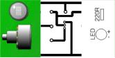 | 166 × 85 (4 KB) | DT Online (talk | contribs) | PCB Designer sample |
You cannot overwrite this file.
File usage
The following 2 pages use this file: