Light Emitting Diode: Difference between revisions
From DT Online
m (Corrected category link) |
mNo edit summary |
||
| Line 1: | Line 1: | ||
[[File:LEDschematic.jpg|300px|right]] | [[File:LEDschematic.jpg|300px|right]] | ||
[http://en.wikipedia.org/wiki/Light-emitting_diode '''Light Emitting Diodes (LED)'''] come in different colours, shapes, sizes and brightness. The more common colours being red, green and yellow. | [http://en.wikipedia.org/wiki/Light-emitting_diode '''Light Emitting Diodes (LED)'''] come in different colours, shapes, sizes and brightness. The more common colours being red, green and yellow. | ||
They are also available in bi-colour and tri-colour versions. Round ones come in 3, 5 and 8mm sizes. There are also rectangular, square and bar types. | They are also available in bi-colour and tri-colour versions. Round ones come in 3, 5 and 8mm sizes. There are also rectangular, square and bar types. | ||
Flashing types are available and [http://en.wikipedia.org/wiki/Seven-segment_display '''seven segment displays'''] are made of a number of LEDs in a particular pattern. | Flashing types are available and [http://en.wikipedia.org/wiki/Seven-segment_display '''seven segment displays'''] are made of a number of LEDs in a particular pattern. | ||
LEDs are easily damaged by excess current therefore it is normal to connect the LED to the supply via a series current limiting '''[[Resistor|resistor]]'''. The value of this resistor is not critical but is usually within the range 100 - 330R. | LEDs are easily damaged by excess current therefore it is normal to connect the LED to the supply via a series current limiting '''[[Resistor|resistor]]'''. The value of this resistor is not critical but is usually within the range 100 - 330R. | ||
Polarity must be observed when connecting LEDs ''(it should be noted that LEDs are damaged by reverse biased voltages larger than about 6 volts)''. | Polarity must be observed when connecting LEDs ''(it should be noted that LEDs are damaged by reverse biased voltages larger than about 6 volts)''. | ||
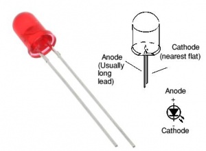
The [http://en.wikipedia.org/wiki/Anode '''Anode'''] is connected to the positive supply via the limiting resistor. The [http://en.wikipedia.org/wiki/Cathode '''Cathode'''] is connected to the negative supply. | The [http://en.wikipedia.org/wiki/Anode '''Anode'''] is connected to the positive supply via the limiting resistor. The [http://en.wikipedia.org/wiki/Cathode '''Cathode'''] is connected to the negative supply. | ||
Revision as of 14:21, 1 June 2015
Light Emitting Diodes (LED) come in different colours, shapes, sizes and brightness. The more common colours being red, green and yellow.
They are also available in bi-colour and tri-colour versions. Round ones come in 3, 5 and 8mm sizes. There are also rectangular, square and bar types.
Flashing types are available and seven segment displays are made of a number of LEDs in a particular pattern.
LEDs are easily damaged by excess current therefore it is normal to connect the LED to the supply via a series current limiting resistor. The value of this resistor is not critical but is usually within the range 100 - 330R.
Polarity must be observed when connecting LEDs (it should be noted that LEDs are damaged by reverse biased voltages larger than about 6 volts).
The Anode is connected to the positive supply via the limiting resistor. The Cathode is connected to the negative supply.
