Thermistor: Difference between revisions
From DT Online
mNo edit summary |
(Added sensor applications) |
||
| (One intermediate revision by the same user not shown) | |||
| Line 1: | Line 1: | ||
[[File:Thermistor. | [[File:Thermistor.png|300px|right]] | ||
__TOC__ | |||
=====Description===== | |||
The resistance of a [http://en.wikipedia.org/wiki/Thermistor '''Thermistor'''] decreases when they are heated ''(negative temperature coefficient type)''. | |||
=====Features and Applications===== | |||
Typical resistance values are 1 kilohm at 25°C and 80 ohms at 100°C. | Typical resistance values are 1 kilohm at 25°C and 80 ohms at 100°C. | ||
Thermistors are suitable for temperature controlled switches and temperature measurement. | [http://en.wikipedia.org/wiki/Thermistor '''Thermistors'''] are suitable for temperature controlled switches and temperature measurement. | ||
A signal of 0.6V, or greater, to the '''BASE''' of the transistor "switches on" the transistor and allows a current to flow in the '''COLLECTOR / EMITTER''' circuit.Transistors also act as '''CURRENT AMPLIFIERS''' since a small base current '''(Ib)''' controls a much larger collector current '''(Ic)'''. The amplification '''''(GAIN - hfe)''''' of a transistor, is given by the equation '''hfe = Ic/Ib''' and is typically several hundreds. ''<span style="color: green">(Note that the use of a variable resistance in the other half of the potential divider circuit allows the sensitivity of the circuit to be adjusted)</span>''. | |||
=====Heat Sensor===== | |||
[[File:HeatSensor.png|200px|right]] | |||
Many "control" circuits are triggered by a signal which is produced by a "potential divider" network. | |||
The signal value depends upon the component values and the supply voltage: | |||
<big>'''Vs=V*R2/(R1+R2)'''</big> | |||
where: | |||
* '''Vs''' is the signal value | |||
* '''V''' is the supply voltage | |||
* '''R1''' is the resistance between the positive supply rail and the base of the transistor | |||
* '''R2''' is the resistance between the negative supply rail and the base of the transistor | |||
The resistance of a [http://en.wikipedia.org/wiki/Thermistor '''thermistor'''] decreases when it is heated. As heat increases, therefore, the resistance of the [http://en.wikipedia.org/wiki/Thermistor '''thermistor'''] decreases and allows the voltage at the base of the transistor to move closer to that of the positive supply rail. | |||
=====Cold Sensor===== | |||
[[File:ColdSensor.png|200px|right]] | |||
As with the '''Heat Sensor''', this circuit is triggered by a signal which is produced by a "potential divider" network and the signal value depends upon the component values and the supply voltage: | |||
<big>'''Vs=V*R2/(R1+R2)'''</big> | |||
where: | |||
* '''Vs''' is the signal value | |||
* '''V''' is the supply voltage | |||
* '''R1''' is the resistance between the positive supply rail and the base of the transistor | |||
* '''R2''' is the resistance between the negative supply rail and the base of the transistor | |||
The resistance of a [http://en.wikipedia.org/wiki/Thermistor '''thermistor'''] decreases when it is heated. In this position therefore, as heat decreases the resistance of the [http://en.wikipedia.org/wiki/Thermistor '''thermistor'''] increases and allows the voltage at the base of the transistor to move closer to that of the positive supply rail. | |||
---- | |||
<span style="color: green">'''Note:'''</span> | |||
* <span style="color: green">When choosing a transistor it is important to make sure that the gain is high enough for the required use and that the maximum current which it can handle is sufficient to drive the output device. e.g. BFY 51 gain > 40 , max Ic = 1 amp.</span> | |||
* <span style="color: green">If the max Ic value is exceeded, the transistor will probably "burn out".</span> | |||
* <span style="color: green">The transistor acts as a '''NOT''' gate ''(inverter)'' since a "high" at the base gives a "low" at the collector. ''(i.e. when the transistor switches on, the collector voltage decreases).''</span> | |||
---- | |||
{{Resistors/Capacitors/Diodes Buyers Guide}} | |||
[[Category:Secondary]] | [[Category:Secondary]] | ||
[[Category:Electronics Components]] | [[Category:Electronics Components]] | ||
Latest revision as of 12:12, 2 November 2016

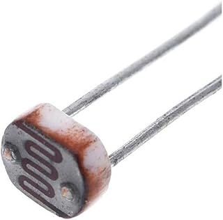
Description
The resistance of a Thermistor decreases when they are heated (negative temperature coefficient type).
Features and Applications
Typical resistance values are 1 kilohm at 25°C and 80 ohms at 100°C.
Thermistors are suitable for temperature controlled switches and temperature measurement.
A signal of 0.6V, or greater, to the BASE of the transistor "switches on" the transistor and allows a current to flow in the COLLECTOR / EMITTER circuit.Transistors also act as CURRENT AMPLIFIERS since a small base current (Ib) controls a much larger collector current (Ic). The amplification (GAIN - hfe) of a transistor, is given by the equation hfe = Ic/Ib and is typically several hundreds. (Note that the use of a variable resistance in the other half of the potential divider circuit allows the sensitivity of the circuit to be adjusted).
Heat Sensor

Many "control" circuits are triggered by a signal which is produced by a "potential divider" network.
The signal value depends upon the component values and the supply voltage:
Vs=V*R2/(R1+R2)
where:
- Vs is the signal value
- V is the supply voltage
- R1 is the resistance between the positive supply rail and the base of the transistor
- R2 is the resistance between the negative supply rail and the base of the transistor
The resistance of a thermistor decreases when it is heated. As heat increases, therefore, the resistance of the thermistor decreases and allows the voltage at the base of the transistor to move closer to that of the positive supply rail.
Cold Sensor

As with the Heat Sensor, this circuit is triggered by a signal which is produced by a "potential divider" network and the signal value depends upon the component values and the supply voltage:
Vs=V*R2/(R1+R2)
where:
- Vs is the signal value
- V is the supply voltage
- R1 is the resistance between the positive supply rail and the base of the transistor
- R2 is the resistance between the negative supply rail and the base of the transistor
The resistance of a thermistor decreases when it is heated. In this position therefore, as heat decreases the resistance of the thermistor increases and allows the voltage at the base of the transistor to move closer to that of the positive supply rail.
Note:
- When choosing a transistor it is important to make sure that the gain is high enough for the required use and that the maximum current which it can handle is sufficient to drive the output device. e.g. BFY 51 gain > 40 , max Ic = 1 amp.
- If the max Ic value is exceeded, the transistor will probably "burn out".
- The transistor acts as a NOT gate (inverter) since a "high" at the base gives a "low" at the collector. (i.e. when the transistor switches on, the collector voltage decreases).