Catenary Arch Model: Difference between revisions
From DT Online
Created article |
mNo edit summary |
||
| (6 intermediate revisions by the same user not shown) | |||
| Line 1: | Line 1: | ||
=====Description===== | |||
During the seventeenth century scientists were offering advice to architects on the design of arches. [http://en.wikipedia.org/wiki/Robert_Hooke '''Robert Hooke'''] proposed a theory but failed to publish his ideas in conventional form, perhaps because of intrigue and jealousy. His conclusions appeared instead in a Latin anagram whose solution read, when translated, | During the seventeenth century scientists were offering advice to architects on the design of arches. [http://en.wikipedia.org/wiki/Robert_Hooke '''Robert Hooke'''] proposed a theory but failed to publish his ideas in conventional form, perhaps because of intrigue and jealousy. His conclusions appeared instead in a Latin anagram whose solution read, when translated, | ||
{| style="border-width: 0px" | {| style="border-width: 0px" | ||
|- | |- | ||
| Line 7: | Line 10: | ||
[[File:GatewayArch.png|300px|right|link=https://en.wikipedia.org/wiki/Gateway_Arch]] | |||
__TOC__ | |||
=====Features and Uses===== | |||
[[File:Catenary1.png|400px|right]] | [[File:Catenary1.png|400px|right]] | ||
There are mathematical equations which define a [https://en.wikipedia.org/wiki/Catenary '''catenary'''] curve, but it is easily created by hanging a short length of chain from the | There are mathematical equations which define a [https://en.wikipedia.org/wiki/Catenary '''catenary'''] curve, but it is easily created by hanging a short length of chain from the edge of a board. | ||
| Line 20: | Line 27: | ||
The thin board could be card or | The thin board could be card or '''[[Manufactured Board|Ply]]''' etc. but if it is clear acrylic for example, an alternative would be to lay it down on a scanner and use '''[[CAD]]''' software to produce the design. | ||
| Line 42: | Line 49: | ||
<div style="clear: both;"></div> | <div style="clear: both;"></div> | ||
[[File:Catenary4.png|400px|right]] | [[File:Catenary4.png|400px|right]] | ||
Arches are very strong at supporting the centrally applied | Arches are very strong at supporting the centrally applied '''[[Dead Load|dead loads]]''' - gently press down on to the top centre to get a sense of this. But arches must also resist '''[[Live Load|live loads]]''' and even sideways forces - which can be very large when a heavy train decelerates from full speed in an emergency stop for example. | ||
| Line 61: | Line 68: | ||
---- | ---- | ||
{{Card Modelling Buyers Guide}} | |||
[[Category:Topics, Projects and Tasks]] | |||
[[Category:Structures Tasks]] | [[Category:Structures Tasks]] | ||
[[Category:Tasks]] | |||
Latest revision as of 19:00, 12 October 2017
Description
During the seventeenth century scientists were offering advice to architects on the design of arches. Robert Hooke proposed a theory but failed to publish his ideas in conventional form, perhaps because of intrigue and jealousy. His conclusions appeared instead in a Latin anagram whose solution read, when translated,
| ''As hangs the flexible line or chain so but inverted will stand the rigid arch''. |
Since the shape taken by a flexible line or chain is called a catenary, Hooke became credited with the discovery of the catenarian arch.

Features and Uses

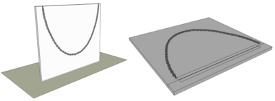
There are mathematical equations which define a catenary curve, but it is easily created by hanging a short length of chain from the edge of a board.
The length is not critical but will determine the size of the arch you finally make so somewhere between 500mm and 1m would suitable for a small model.

Carefully lay the board down to draw around it and produce a curve then draw another curve about 25mm inside it to create an arch design.
The thin board could be card or Ply etc. but if it is clear acrylic for example, an alternative would be to lay it down on a scanner and use CAD software to produce the design.

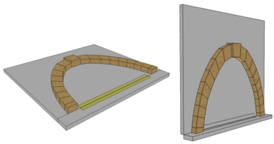
Divide the curve into a number of sections, using more towards the top so that pieces of wood strip can be cut to follow closely the shape of the curve. Wood of about 20mm to 25mm thickness should suffice and can be cut accurately using a Precision Mitre Saw for example.
If not done previously, tape or hinge a strip of board along the bottom edge so the model arch can be raised to the vertical and left standing on the thin strip.
You may need to make two small wedges, and glue one to each foot of the arch, so that it can stand on a flat surface.
You may also need to hold a piece of card over the blocks to keep them in position as you raise the arch.
Carefully lower the supporting board to leave the upright arch and, if the wood blocks are cut reasonably accurately, the arch should stand and be self-supporting without the need for any glue.

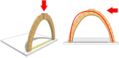
Arches are very strong at supporting the centrally applied dead loads - gently press down on to the top centre to get a sense of this. But arches must also resist live loads and even sideways forces - which can be very large when a heavy train decelerates from full speed in an emergency stop for example.
For an arch, the worst position for live loads is when just half the span is loaded. The pattern of weights acting on the voussoirs is now skewed and the resulting thrust line is skewed too. The voussoirs have to be thick enough so that all thrust lines for all possible patterns of live load are just within their thickness.
The calculation of the necessary thickness is very complex even using the computers of today. Traditionally, architects used simple rules which had been arrived at by trial and error. The arches we see today are the ones where they got it right!
If the thrust line falls outside the voussoirs then the force cannot be passed from stone to stone by simple compression and the joints will open out, forming a hinge in the arch. As the load passes, these joints will open and close but the bridge should remain standing. One of the great strengths of the arch form is that it requires four separate hinge points before it will collapse.
If your model arch is touched gently it will sway like a chain but it should not collapse.
Note: This same building technique can be adapted to build other designs of arch - eg a Roman Arch. Simply draw out the required arch design on a flat board, build it, then raise to the vertical.


