Electric Bells and Buzzers: Difference between revisions
From DT Online
m Added Templates |
mNo edit summary |
||
| (17 intermediate revisions by the same user not shown) | |||
| Line 1: | Line 1: | ||
<div class="floatright"><dtamazon type="search" search="Electric Bell"><img alt="ElectricDoorBell.png" src="/images/thumb/1/1f/ElectricDoorBell.png/300px-ElectricDoorBell.png" width="300" height="214" srcset="/images/1/1f/ElectricDoorBell.png 1.5x, /images/1/1f/ElectricDoorBell.png 2x" /></a></dtamazon></div> | |||
__TOC__ | |||
=====Bells===== | |||
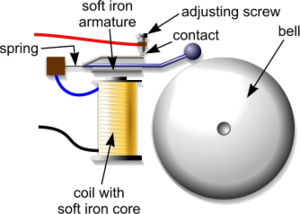
[http://en.wikipedia.org/wiki/Electric_bell '''Electric bells'''] are electromagnetic devices with contacts arranged so that once the coil is energized the [http://en.wikipedia.org/wiki/Armature_%28electrical_engineering%29 '''armature'''] is attracted to it and the circuit is broken. | [http://en.wikipedia.org/wiki/Electric_bell '''Electric bells'''] are electromagnetic devices with contacts arranged so that once the coil is energized the [http://en.wikipedia.org/wiki/Armature_%28electrical_engineering%29 '''armature'''] is attracted to it and the circuit is broken. | ||
Once broken the coil is de-energized and the armature springs back to complete the circuit once more. | Once broken the coil is de-energized and the armature springs back to complete the circuit once more. | ||
Each time the armature is attracted to the coil the hammer strikes the bell. This continues in an oscillatory manner until the power is switched off. | Each time the armature is attracted to the coil the hammer strikes the bell. This continues in an oscillatory manner until the power is switched off. | ||
[[File:OldBuzzer.png|200px|right|link=https://archive.org/stream/stnicholasserial322dodg/stnicholasserial322dodg#page/n688/mode/1up]] | |||
Bells normally work on low voltage typically 6 volts. Bells create a distinct ringing sound and can be used as outputs for alarm circuits. | |||
=====Buzzers===== | |||
At their simplest, electro-mechanical buzzers [http://en.wikipedia.org/wiki/Buzzer '''Buzzers'''] can be similar but without the hammer and bell and the 'buzzing' created by the vibrating relay contacts - amplified by being attached to a sounding board of some form. | |||
<div class="floatright"><dtamazon type="search" search="pcb mount Buzzer"><img alt="Buzzer2.png" src="/images/thumb/4/41/Buzzer2.png/200px-Buzzer2.png" width="200" height="117" srcset="/images/thumb/4/41/Buzzer2.png/300px-Buzzer2.png 1.5x, /images/4/41/Buzzer2.png 2x" /></a></dtamazon></div> | |||
Most commercially available [http://en.wikipedia.org/wiki/Buzzer '''Buzzers'''] however, cause an electro-magnet to vibrate a metal disc or plate by supplying it with an oscillating current. [https://en.wikipedia.org/wiki/Direct_current '''Direct Current (D.C.)'''] [http://en.wikipedia.org/wiki/Buzzer '''Buzzers'''] require a drive circuit to provide this, which is usually built into the device. | |||
Buzzers are usually of the single tone variety in the lower frequency ranges and are normally rated between 6 and 24 volts. They are suitable for alarm circuits, test equipment, timing and control. | |||
To achieve maximum sound output from the device it should be firmly mounted. | |||
[[File:BuzzerCircuit.png|200px|right]] | |||
=====Bells and Buzzers in a Transistor Circuit===== | |||
When a voltage is applied to the terminals of the bell or buzzer, they emit sounds suitable for alarm circuits and warning applications. To ensure maximum sound output, the bell or buzzer should be firmly mounted. | |||
The purpose of the '''IN4001 [[Diode]]''' shown is to restrict any [https://en.wikipedia.org/wiki/Counter-electromotive_force '''Back EMF'''] resulting from the Transistor being used to switch an inductive device ''(e.g. '''[[Electric Motor]]''', '''[[Solenoid]]''' or '''[[Relays|Relay]]'''). | |||
[[File:PiezoTransducer.jpg|200px|right]] | |||
=====Piezo Transducer===== | |||
When an electric current is passed through some ceramic or crystal materials ''(e.g. quartz)'' the '''[[Crystalline Structures|Crystalline Structure]]''' expands slighty. If a piece of such a [https://en.wikipedia.org/wiki/Piezoelectricity '''Piezoelectric Electric'''] material is '''[[Laminating|Laminated]]''' to a thin metal plate, or diaphragm, its expansion will cause the diaphragm to distort slightly. When excited by an oscillating current, it will vibrate the diaphragm and a high frequency sound will be emitted - see '''[[Piezo Transducer]]'''. | |||
[ | [[File:555PiezoDriver.png|200px|right]] | ||
When used in [https://en.wikipedia.org/wiki/Direct_current '''Direct Current (D.C.)'''] applications they too require a drive circuit to provide an oscillating current. This can be built into the device but is often provided separately. A suitable [https://en.wikipedia.org/wiki/Electronic_oscillator '''Oscillator'''] circuit for both electro-mechanical and Piezo transducers is to use a 555 Timer configured in [https://en.wikipedia.org/wiki/555_timer_IC#Astable '''Astable'''] mode as shown. | |||
This forms the basis of the [https://en.wikipedia.org/wiki/Piezoelectric_speaker '''Piezoelectric Buzzers'''] or speakers which are commonly used in electronic devices and are sometimes used as [https://en.wikipedia.org/wiki/Tweeter '''Tweeters'''] in less-expensive speaker systems. They can operate over a wide voltage ''(e.g. 3 to 250V)'', less than 30mA current consumption and produce a higher rated frequency. | |||
<div style="clear: both;"></div> | |||
{{Bells/Buzzers/Mics/Speakers Buyers Guide}} | |||
[[Category:Primary]] | |||
[[Category:Secondary]] | |||
[[Category:Electronics Components]] | |||
Latest revision as of 11:28, 28 January 2018
Bells
Electric bells are electromagnetic devices with contacts arranged so that once the coil is energized the armature is attracted to it and the circuit is broken.
Once broken the coil is de-energized and the armature springs back to complete the circuit once more.
Each time the armature is attracted to the coil the hammer strikes the bell. This continues in an oscillatory manner until the power is switched off.
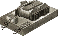
Bells normally work on low voltage typically 6 volts. Bells create a distinct ringing sound and can be used as outputs for alarm circuits.
Buzzers
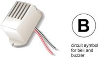
At their simplest, electro-mechanical buzzers Buzzers can be similar but without the hammer and bell and the 'buzzing' created by the vibrating relay contacts - amplified by being attached to a sounding board of some form.
Most commercially available Buzzers however, cause an electro-magnet to vibrate a metal disc or plate by supplying it with an oscillating current. Direct Current (D.C.) Buzzers require a drive circuit to provide this, which is usually built into the device.
Buzzers are usually of the single tone variety in the lower frequency ranges and are normally rated between 6 and 24 volts. They are suitable for alarm circuits, test equipment, timing and control.
To achieve maximum sound output from the device it should be firmly mounted.
Bells and Buzzers in a Transistor Circuit
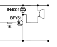
When a voltage is applied to the terminals of the bell or buzzer, they emit sounds suitable for alarm circuits and warning applications. To ensure maximum sound output, the bell or buzzer should be firmly mounted.
The purpose of the IN4001 Diode shown is to restrict any Back EMF resulting from the Transistor being used to switch an inductive device (e.g. Electric Motor, Solenoid or Relay).
Piezo Transducer
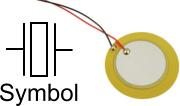
When an electric current is passed through some ceramic or crystal materials (e.g. quartz) the Crystalline Structure expands slighty. If a piece of such a Piezoelectric Electric material is Laminated to a thin metal plate, or diaphragm, its expansion will cause the diaphragm to distort slightly. When excited by an oscillating current, it will vibrate the diaphragm and a high frequency sound will be emitted - see Piezo Transducer.
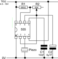
When used in Direct Current (D.C.) applications they too require a drive circuit to provide an oscillating current. This can be built into the device but is often provided separately. A suitable Oscillator circuit for both electro-mechanical and Piezo transducers is to use a 555 Timer configured in Astable mode as shown.
This forms the basis of the Piezoelectric Buzzers or speakers which are commonly used in electronic devices and are sometimes used as Tweeters in less-expensive speaker systems. They can operate over a wide voltage (e.g. 3 to 250V), less than 30mA current consumption and produce a higher rated frequency.
