Loci: Difference between revisions
From DT Online
(Created Loci) |
(Completed Loci) |
||
| Line 1: | Line 1: | ||
The [https://en.wikipedia.org/wiki/Locus_%28mathematics%29 '''Locus of a Point'''] is the path traced by a point as it moves in accordance with set conditions and constraints. | The [https://en.wikipedia.org/wiki/Locus_%28mathematics%29 '''Locus of a Point'''] is the path traced by a point as it moves in accordance with set conditions and constraints. The plural of [http://www.mathopenref.com/locus.html '''Locus'''] is '''Loci'''. | ||
More practically it sometimes necessary to know the path traced by the ends of pieces of machinery | For example: the locus of all points a set distance from another point is a circle; the locus of all points equi-distant from the ends of a line is the [[Basic Constructions|perpendicular bisector]] of the line; and the locus of all points a set distance from a given line are lines parallel to it ''(or an oval if the locus continues round the ends of the line)'' | ||
More practically it sometimes necessary to know the path traced by the ends of pieces of machinery to check clearances, estimate the velocities at different parts of a linkage ''(perhaps to calculate momentum)'' or to design guarding for example. The general method is to draw the linkage or mechanism in several ‘freeze frame’ positions then draw a smooth curve through the plotted points. | |||
{| cellpadding="5" | {| cellpadding="5" | ||
|- | |- | ||
| ''' | | '''Plotting Loci on a Crank and Slider Mechanism''' | ||
| <span style="color:#B00000"> | | <span style="color:#B00000"> | ||
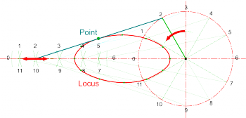
* | * Draw a schematic of the crank and slider and divide the crank rotation into a number of equal divisions ''(say, 12)'' | ||
| [[File: | * Number the crank positions and, with radius set to the length of the connecting rod, strike arcs from each position along the horizontal line which the piston is constrained to slide along. | ||
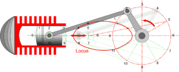
* If the requirement is for the locus of the centre of the connecting rod, then mark these points on each position and join with a smooth curve as shown. | |||
* It may sometimes be neccessary to draw in additional details of the mechanisms, to test clearances for example. | |||
* Loci on parts of other mechanisms can be plotted using a similar process - i.e. draw the mechanism in different positions and connect plotted points to create the locus. | |||
</span> | |||
| [[File:LociCrankSlider.png |350px|right]] | |||
[[File:LociPistonCrank2.png|350px|right]] | |||
|} | |} | ||
[[Category:Secondary]] | |||
[[Category:Geometry]] | |||
[[Category:Mechanisms]] | |||
Revision as of 19:40, 26 February 2015
The Locus of a Point is the path traced by a point as it moves in accordance with set conditions and constraints. The plural of Locus is Loci.
For example: the locus of all points a set distance from another point is a circle; the locus of all points equi-distant from the ends of a line is the perpendicular bisector of the line; and the locus of all points a set distance from a given line are lines parallel to it (or an oval if the locus continues round the ends of the line)
More practically it sometimes necessary to know the path traced by the ends of pieces of machinery to check clearances, estimate the velocities at different parts of a linkage (perhaps to calculate momentum) or to design guarding for example. The general method is to draw the linkage or mechanism in several ‘freeze frame’ positions then draw a smooth curve through the plotted points.
| Plotting Loci on a Crank and Slider Mechanism |
|
|

