Resistor: Difference between revisions
From DT Online
(Added Sections) |
mNo edit summary |
||
| Line 64: | Line 64: | ||
=====Resistors in Circuits===== | =====Resistors in Circuits===== | ||
Resistors can be joined end to end in [http://en.wikipedia.org/wiki/Series_and_parallel_circuits#Series_circuits '''series'''].[[File:ResistorSeries.jpg|200px|right]] In this arrangement the total resistance is equal to the value of all the resistors added together - i.e. : R''(total)''= R1 + R2 + R3...etc | Resistors can be joined end to end in [http://en.wikipedia.org/wiki/Series_and_parallel_circuits#Series_circuits '''series'''].[[File:ResistorSeries.jpg|200px|right]] | ||
In this arrangement the total resistance is equal to the value of all the resistors added together - i.e. : R''(total)''= R1 + R2 + R3...etc | |||
Revision as of 10:38, 1 June 2015
Resistors are used to control the flow of current in a circuit, by ‘resisting’ the flow of electrons.
The value of a resistor is measured in ohms (symbol: Ω). This unit is named after Georg Ohm, the German physicist and mathematician who described Ohm's Law
Resistance (R) is defined as the ratio of the potential difference (voltage) across a conductor, to the current flowing through it - ie.: Resistance (ohms) = Voltage (volts) / Current (amps)
The unit of voltage (symbol: V) is named after Alessandro Volta and the unit of current (symbol: A) is named after André-Marie Ampère
Resistor Colour Code
Resistors are available in values from fractions of ohms up to many millions of ohms (Megohms) although only certain ‘preferred’ values are readily available.
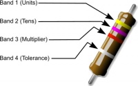
To identify the resistance value of resistors a ‘colour code’ system is often used.
The colours are shown on a series of colour bands at one end of the resistor. 2 colour bands plus a multiplier are shown but sometimes there is a 3rd colour band before the multiplier to show hundredths.
At the other end of the resistor there can also be a gold or silver band to denote the accuracy tolerance of the value displayed.
The colour code is really just an extension of the colours of the rainbow and so a similar mnemonic could be devised to help remember them
- e.g. Big Brawny Richard of York Gave Battle in Very Grey Weather
Activity: Can you think of your own way of remembering the colour code?
Resistor Types and Sizes
In most circuits 1/3 watt to 1 watt carbon resistors are suitable, but if the current is likely to be high, wire wound resistors should be used. Carbon and carbon film resistors are generally available up to 2 watts. Above that value wire wound resistors are used - commonly available up to 17 watts.
Resistors are available with different tolerance values - these define how exact the value of the resistor is likely to be when compared with its marked value. For example, a 100R 10% resistor could have a value anywhere between 90R and 110R. Higher precision is not usually needed, but where necessary, higher precision resistors can be obtained, but at extra expense.
Potentiometer
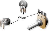
Variable resistors or potentiometers are used where the flow of current in a circuit needs to be occasionally varied such as for:
- Volume Control
- Frequency Control
- Output Voltage Control
They are available in a range of sizes.
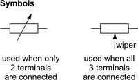
The international symbol for a variable resistor or potentiometer when drawing circuit diagrams is shown opposite
Resistors in Circuits
Resistors can be joined end to end in series.
In this arrangement the total resistance is equal to the value of all the resistors added together - i.e. : R(total)= R1 + R2 + R3...etc
Resistors may also be connected together in parallel.
In this arrangement the total resistance is calculated as follows:
- ___1___ = _______1________
- R (Total) R1 + R2 + R3...etc
or
- R (Total) = _____R1xR2xR3_____
- R1xR2+R2xR3+R3xR1
- R (Total) = _____R1xR2xR3_____
Time Constant
Capacitors may also be connected together end to end in series with a resistor to create a resistor–capacitor circuit (RC circuit) in which a capacitor charges or discharges through a resistor for a known period of time known as the time constant
In this arrangement the time constant is calculated as follows:
- T(seconds)= C(farads) x R(ohms)


