Modelling Gears: Difference between revisions
From DT Online
mNo edit summary |
m (Corrected spelling) |
||
| Line 46: | Line 46: | ||
|- | |- | ||
| [https://en.wikipedia.org/wiki/Gear#Cage_gear '''Lantern Gear'''] | | [https://en.wikipedia.org/wiki/Gear#Cage_gear '''Lantern Gear'''] | ||
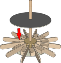
| Also known as '''Cage Gears''' and so named because of their resemblance to those items. They are simply made by gluing short | | Also known as '''Cage Gears''' and so named because of their resemblance to those items. They are simply made by gluing short lengths of '''Dowel''' between two discs of Card, Ply or MDF. | ||
| Line 85: | Line 85: | ||
|- | |- | ||
| rowspan=2|'''Gear Geometry''' | | rowspan=2|'''Gear Geometry''' | ||
| rowspan=2|Gears can be used to speed up or slow down an axle they are connected to but if they are to '''Mesh''' at all, the gear teeth must all be the same size. | | rowspan=2|Different size Gears can be used to speed up or slow down an axle they are connected to but if they are to '''Mesh''' at all, the gear teeth must all be the same size. | ||
Gears can be imagined to '''Mesh''' as if they were plain circles ''(i.e. with no teeth at all)''. These imaginary circles are known as the '''Pitch Circles''' and it is the length of each tooth along the circumference of the | Gears can be imagined to '''Mesh''' as if they were plain circles ''(i.e. with no teeth at all)''. These imaginary circles are known as the '''Pitch Circles''' and it is the length of each tooth along the circumference of the '''Pitch Circles''' which matters. This distance is known as the '''Circular Pitch''' and must stay the same for any two '''Meshing''' gears. | ||
To achieve this, the diameter of the '''Pitch Circles''' have to change with the number of teeth required | To achieve this, the diameter of the '''Pitch Circles''' have to change with the number of teeth required - a 6 tooth gear therefore would have to be only half the diameter of a 12 tooth gear. | ||
---- | ---- | ||
<span style="color: green">'''Note:''' | <span style="color: green">'''Note:''' | ||
Revision as of 15:37, 31 March 2016
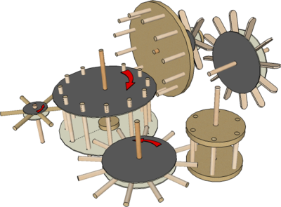
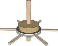
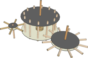
Working model Gears can be made by arranging short lengths of material (e.g. Dowel, Stripwood, Lolly Sticks, Matchsticks, Cocktail Sticks) around discs of Card, Ply or MDF.
Gears provide an alternative to Pulleys when transfering power between revolving shafts or axles. Gears have to be positioned more carefully than Pulleys if they are to Mesh successfully. Two Meshing Gears will always rotate in opposite directions whereas Pulleys will only do so if the Drive Belt is given a half twist.
'Real' Gears provide a much more positive drive than Pulleys and can transfer much more power but this is not usually of concern when making models. The construction of Stripwood model Gears, however, can lend some realistion to models such as Windmills and Watermills.
Construction
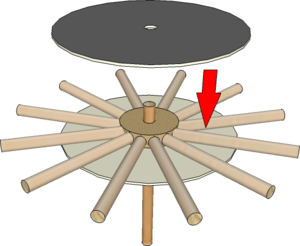
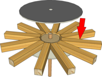
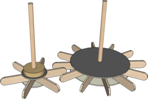
| Construction | Simple Gears for working models can be made by arranging a number of Spokes around a disc of Card, Ply or MDF.
|
|
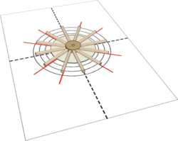
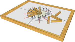
| Templates and Jigs | A degree of accuracy is required when spacing the Spokes around the discs.
Note: Cover the Template with tracing paper to stop glue sticking to it. If required, an assembly Jig can be made by gluing the Template on to a piece of Softwood or Insulation Board and fixing small Nails or Panel Pins in place to locate the Spokes. |
|
Lantern Gear
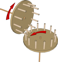
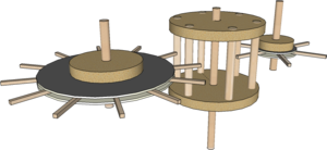
| Lantern Gear | Also known as Cage Gears and so named because of their resemblance to those items. They are simply made by gluing short lengths of Dowel between two discs of Card, Ply or MDF.
|
|
| Peg Gear | These Mesh with each other or with a Lantern Gear and can be regarded as another Lantern Gear with one disc removed.
Note: The large gear or Brakewheel found in old Windmills, had wooden teeth (i.e. made from Hornbeam or Fruitwood). This made for quiet running and easy gear tooth replacement when worn . . . but wear was minimised by having an odd number of teeth such that the same two teeth did not keep coming into contact with each other. |
Spur Gears
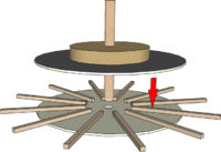
| Spur Gear | The simplest form of Gear is a rotating disc with straight teeth projecting from its rim.
|
Meshing Gears
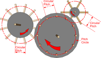
| Gear Geometry | Different size Gears can be used to speed up or slow down an axle they are connected to but if they are to Mesh at all, the gear teeth must all be the same size.
Note: As with Pulleys, a 6 tooth Driver gear would cause a 12 tooth Driven Gear to rotate at half speed - and vice versa. |
|
