Beam Bridge Models: Difference between revisions
From DT Online
m (Added Category) |
(Added Template) |
||
| Line 3: | Line 3: | ||
[[File:TestingPaperBeam2.png|400px|right]] | [[File:TestingPaperBeam2.png|400px|right]] | ||
__TOC__ | |||
=====Description===== | |||
Place two wooden blocks or similar supports 250mm apart then design a beam bridge to span the gap between them using '''[[Paper and Card|A4 paper]]''' or thin card. Try different designs and test each one by loading it until it fails. | Place two wooden blocks or similar supports 250mm apart then design a beam bridge to span the gap between them using '''[[Paper and Card|A4 paper]]''' or thin card. Try different designs and test each one by loading it until it fails. | ||
| Line 8: | Line 12: | ||
You can either add small weights to the top centre of the beam or suspend a paper cup or similar underneath. In either case you may wish to place a small section (say, 50mm square) of thicker card in the centre of the beam to spread the load a little. | You can either add small weights to the top centre of the beam or suspend a paper cup or similar underneath. In either case you may wish to place a small section (say, 50mm square) of thicker card in the centre of the beam to spread the load a little. | ||
=====Testing===== | |||
Make a sketch of each design and record the results: | Make a sketch of each design and record the results: | ||
| Line 15: | Line 21: | ||
*how deep was your beam? | *how deep was your beam? | ||
*what types of traffic or services could pass over your beam? | *what types of traffic or services could pass over your beam? | ||
| Line 24: | Line 29: | ||
*was it the widest beams that were strongest or the deepest? | *was it the widest beams that were strongest or the deepest? | ||
=====Modern Steel Beams===== | |||
You will notice a difference if you try bending a ruler first on its side and then on edge. The steel girders or [http://en.wikipedia.org/wiki/Rolled_Steel_Joist '''joists'''] seen in building construction are often made in an 'I' section which is taller than it is wide. The narrow 'flanges' at top and bottom are there mainly to stop the beam buckling and twisting under load - and to provide a flat supporting surface. | You will notice a difference if you try bending a ruler first on its side and then on edge. The steel girders or [http://en.wikipedia.org/wiki/Rolled_Steel_Joist '''joists'''] seen in building construction are often made in an 'I' section which is taller than it is wide. The narrow 'flanges' at top and bottom are there mainly to stop the beam buckling and twisting under load - and to provide a flat supporting surface. | ||
| Line 45: | Line 52: | ||
</span> | </span> | ||
---- | ---- | ||
=====Traditional Timber Beams===== | |||
[[File:Cleaving.jpg|200px|right|Cleaving a 'green' tree trunk using axe and wedges|link=http://en.wikipedia.org/wiki/Cleaving_axe]] | [[File:Cleaving.jpg|200px|right|Cleaving a 'green' tree trunk using axe and wedges|link=http://en.wikipedia.org/wiki/Cleaving_axe]] | ||
In contrast to modern practice, if you look inside a Medieval [http://en.wikipedia.org/wiki/Timber_framing '''timber-framed'''] house, such as the [http://en.wikipedia.org/wiki/Merchant_Adventurers%27_Hall '''Merchant Adventurers' Hall'''] in York for example, you will notice that roof and floor beams are often wider than they are deep. | In contrast to modern practice, if you look inside a Medieval [http://en.wikipedia.org/wiki/Timber_framing '''timber-framed'''] house, such as the [http://en.wikipedia.org/wiki/Merchant_Adventurers%27_Hall '''Merchant Adventurers' Hall'''] in York for example, you will notice that roof and floor beams are often wider than they are deep. | ||
| Line 53: | Line 63: | ||
The result is a very heavy and over-sized beam - but trees at that time were plentiful! | The result is a very heavy and over-sized beam - but trees at that time were plentiful! | ||
{{Card Modelling Buyers Guide}} | |||
[[Category:Primary Technology]] | [[Category:Primary Technology]] | ||
Revision as of 09:48, 31 May 2016
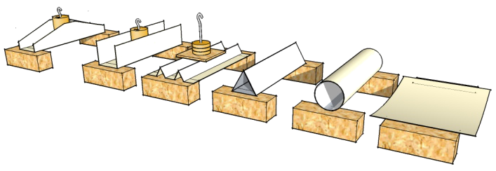
The effectiveness of a material for bridge building depends on the way it is used. Paper or thin card might not appear to be able to support much load but it is possible to greatly increase its strength by manipulating its shape.
Description
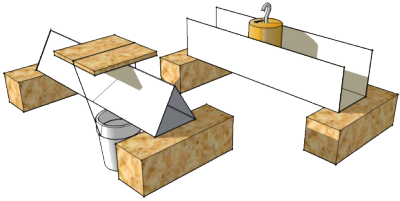
Place two wooden blocks or similar supports 250mm apart then design a beam bridge to span the gap between them using A4 paper or thin card. Try different designs and test each one by loading it until it fails.
You can either add small weights to the top centre of the beam or suspend a paper cup or similar underneath. In either case you may wish to place a small section (say, 50mm square) of thicker card in the centre of the beam to spread the load a little.
Testing
Make a sketch of each design and record the results:
- how much load did it take?
- how wide was your beam?
- how deep was your beam?
- what types of traffic or services could pass over your beam?
. . . or even through your beam . . . the Britannia Bridge across the Menai Strait was originally designed and built by Robert Stephenson as a tubular bridge of wrought iron rectangular box-section spans for carrying rail traffic inside but had to be rebuilt following a fire in 1970.

- were some shapes stronger than others?
- was it the widest beams that were strongest or the deepest?
Modern Steel Beams
You will notice a difference if you try bending a ruler first on its side and then on edge. The steel girders or joists seen in building construction are often made in an 'I' section which is taller than it is wide. The narrow 'flanges' at top and bottom are there mainly to stop the beam buckling and twisting under load - and to provide a flat supporting surface.
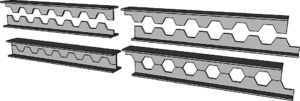
Lightweight steel joists have holes along the centre, or Neutral Axis, of the vertical web. You may also see these used in the chassis of trucks for example.
In a Castellated Beam, these are created by cutting a standard RSJ, separating the pieces to re-align, then welding back together along the Neutral Axis.
This produces a lightweight beam and also increases the depth. All holes are along the centre of the web where there is least stress and the weld is along the Neutral Axis, where there is little or no stress.
A Cellular Beam is the modern version of the traditional "'castellated'" beam and results in a beam approximately 40–60% deeper than the original RSJ.
Note: If beams or joists have to be drilled to accept pipes or wiring etc., it is best to pass them close to the Neutral Axis to avoiding weakening the beam
Traditional Timber Beams
In contrast to modern practice, if you look inside a Medieval timber-framed house, such as the Merchant Adventurers' Hall in York for example, you will notice that roof and floor beams are often wider than they are deep.
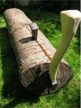
This arises from the need to make things out of logs and tree trunks, without modern high-tech saws to cut sections from the starting material stock. A freshly felled 'green' log is 'cleaved' down its centre using axes and wedges. The resulting half-round section is squared off using axes, adzes and draw knives but the original central 'cleaved' surface provides a good flat surface on which to fix roofs and floors.
The result is a very heavy and over-sized beam - but trees at that time were plentiful!


