Electric Bells and Buzzers: Difference between revisions
From DT Online
mNo edit summary |
mNo edit summary |
||
| Line 32: | Line 32: | ||
=====Bells and Buzzers in Circuit===== | =====Bells and Buzzers in Circuit===== | ||
When a voltage is applied to the terminals of the buzzer, | When a voltage is applied to the terminals of the bell or buzzer, they emit sounds suitable for alarm circuits and warning applications. To ensure maximum sound output, the bell or buzzer should be firmly mounted. | ||
Revision as of 17:13, 2 November 2016
Bells
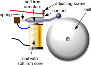
Electric bells are electromagnetic devices with contacts arranged so that once the coil is energized the armature is attracted to it and the circuit is broken.
Once broken the coil is de-energized and the armature springs back to complete the circuit once more.
Each time the armature is attracted to the coil the hammer strikes the bell. This continues in an oscillatory manner until the power is switched off.
Bells normally work on low voltage typically 6 volts. Bells are used as outputs for alarm circuits.
Buzzers
Buzzers are usually of the single tone variety and are normally rated between 6 and 24 volts.
They are suitable for alarm circuits, test equipment, timing and control.
To achieve maximum sound output from the device it should be firmly mounted.
Bells and Buzzers in Circuit
When a voltage is applied to the terminals of the bell or buzzer, they emit sounds suitable for alarm circuits and warning applications. To ensure maximum sound output, the bell or buzzer should be firmly mounted.
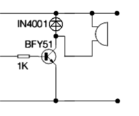
The purpose of the IN4001 Diode shown is to restrict any Back EMF resulting from the Transistor being used to switch an inductive device (e.g. Electric Motor, Solenoid or Relay).


