Precision Marking and Measuring: Difference between revisions
From DT Online
Created Article |
mNo edit summary |
||
| (6 intermediate revisions by the same user not shown) | |||
| Line 1: | Line 1: | ||
[[File:UsingSurfacePlate.png | | [[File:UsingSurfacePlate.png |300px|right]] | ||
__TOC__ | |||
Engineering components can be irregular in shape and so a line or surface has to be chosen as the [https://en.wikipedia.org/wiki/Datum_reference '''Datum'''] - i.e. the place from where all measurements will start . The | =====Description===== | ||
When components have to be made to a precise measurement, in [https://en.wikipedia.org/wiki/Engineering '''Engineering'''] for example, it is important to be able to mark them out and test their dimensions as accurately as possible. A sharp '''[[Scriber]]''' is used to mark lines and the surface of [https://en.wikipedia.org/wiki/Carbon_steel '''bright drawn mild steel (BDMS)'''] may first be coated with [https://en.wikipedia.org/wiki/Marking_blue '''Marking Blue'''] to ensure the lines can be seen easily ''([https://en.wikipedia.org/wiki/Rolling_%28metalworking%29 '''black rolled mild steel'''] or [https://en.wikipedia.org/wiki/Cast_iron '''cast iron'''] could be rubbed with chalk for similar reasons)''. | |||
=====Features and Applications===== | |||
Engineering components can be irregular in shape and so a line or surface has to be chosen as the [https://en.wikipedia.org/wiki/Datum_reference '''Datum'''] - i.e. the place from where all measurements will start . The datum can be a centre line or a straight edge ''(in woodwork, this would be the '''[[Face Side and Face Edge|Face Side]]''' or '''[[Face Side and Face Edge|Face Edge]]''')''. Often, and especially with castings or mouldings, the workpiece is held in relation to a flat surface to enable these reference lines to be scribed in the first place. Testing of properties such as flatness, roundness or parallelness can also be achieved by checking against a known flat surface. | |||
---- | ---- | ||
<span style="color: green">'''Note:''' | <span style="color: green">'''Note:''' | ||
| Line 13: | Line 20: | ||
| [https://en.wikipedia.org/wiki/Surface_plate '''Surface Plate'''] | | [https://en.wikipedia.org/wiki/Surface_plate '''Surface Plate'''] | ||
| An accurately machined flat surface usually made from '''Cast Iron''' for stability ''(larger versions may be called a '''Surface Table''')''. Work may be placed on here and heights measured from the surface for example. | | An accurately machined flat surface usually made from '''Cast Iron''' for stability ''(larger versions may be called a '''Surface Table''')''. Work may be placed on here and heights measured from the surface for example. | ||
---- | |||
<span style="color: green">'''Note:''' | |||
For most applications in '''[[Design and Technology]]''' a piece of [https://en.wikipedia.org/wiki/Float_glass '''Float Glass'''], as used in good quality mirrors for example, would provide an adequately flat reference surface. | |||
</span> | |||
---- | |||
| [[File:SurfacePlate.png|250px|right]] | | [[File:SurfacePlate.png|250px|right]] | ||
|- | |- | ||
| '''Scribing Block''' | | '''Scribing Block''' | ||
| A device for holding a '''Scriber''' to mark lines at a given height for the '''''datum surface''''' | | A device for holding a '''[[Scriber]]''' to mark lines at a given height for the '''''datum surface''''' | ||
| [[File:ScribingBlock.png|100px|right]] | | [[File:ScribingBlock.png|100px|right]] | ||
|- | |- | ||
| Line 39: | Line 51: | ||
| Used to check that a component is parallel to the '''Surface Plate''' or flat or to check a bar is round by rotating it on '''Vee Blocks''' whilst a '''DTI''' is held against it. | | Used to check that a component is parallel to the '''Surface Plate''' or flat or to check a bar is round by rotating it on '''Vee Blocks''' whilst a '''DTI''' is held against it. | ||
| [[File:DialGauge.png|200px|right]] | | [[File:DialGauge.png|200px|right]] | ||
|- | |||
| [https://en.wikipedia.org/wiki/Height_gauge '''Height Gauges'''] | |||
| Similar to '''Surface Gauges''' but differ in that they include a scale or read-out to provide measurement directly. They are used in conjunction with a '''Surface Plate''' accurately to measure heights from a common datum ''(i.e. the underside of the cast iron base)''. | |||
| [[File:HeightGauge.jpg |200px|right]] | |||
|- | |||
| [https://en.wikipedia.org/wiki/Feeler_gauge '''Feeler Gauges'''] | |||
| These are thin strips of metal ground very accurately to thickness. They are used to measure small gaps ''(e.g. spark plug gaps)'' or clearances between two parts. Imperial measuremnets are in thousandths of an inch ''(‘Thous’)'' and metric gauges in hundredths of a millimetre. | |||
| [[File:FeelerGauge.jpg |200px|right]] | |||
|- | |||
| [https://en.wikipedia.org/wiki/Wire_gauge '''Wire Gauges'''] | |||
| Used quickly to measure the diameter of thin wires ''(e.g. guitar strings)'' - or the thickness of metal sheets. Wire and sheet is now measured in millimetres and '''Wire Gauges''' reflect this, but traditionally, they were used to measure in [https://en.wikipedia.org/wiki/Standard_wire_gauge '''Standard Wire Gauge (SWG)''']. This has now been superseded but wire gauges are available with dual scales. | |||
| [[File:Wire Gauge.jpg |200px|right]] | |||
|- | |||
| [https://en.wikipedia.org/wiki/Thread_pitch_gauge '''Screw Pitch Gauges'''] | |||
| Used as a means of measuring quickly the coarseness ''(or fineness)'' of a given screwthread. For Imperial threads this is usually given as the number of threads per inch and, for metric threads, the measurement of the actual thread [https://en.wikipedia.org/wiki/Screw_thread#Lead.2C_pitch.2C_and_starts '''pitch'''] is provided. Such information is needed when matching screwthreads and, more particuarly, when cutting a screwthread on a '''[[Centre Lathe]]'''. | |||
| [[File:ScrewPitchGauge.jpg|200px|right]] | |||
|} | |} | ||
{{Precision Marking Buyers Guide}} | |||
[[Category:Secondary]] | |||
[[Category:Marking and Measuring Tools]] | |||
Latest revision as of 08:40, 25 November 2016
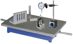
Description
When components have to be made to a precise measurement, in Engineering for example, it is important to be able to mark them out and test their dimensions as accurately as possible. A sharp Scriber is used to mark lines and the surface of bright drawn mild steel (BDMS) may first be coated with Marking Blue to ensure the lines can be seen easily (black rolled mild steel or cast iron could be rubbed with chalk for similar reasons).
Features and Applications
Engineering components can be irregular in shape and so a line or surface has to be chosen as the Datum - i.e. the place from where all measurements will start . The datum can be a centre line or a straight edge (in woodwork, this would be the Face Side or Face Edge). Often, and especially with castings or mouldings, the workpiece is held in relation to a flat surface to enable these reference lines to be scribed in the first place. Testing of properties such as flatness, roundness or parallelness can also be achieved by checking against a known flat surface.
Note: It is virtually impossible to make anything to an exact size. In practice components are made as accurately as they need to be to function. The degree of error allowable is known as the Tolerance and this varies with the type of work being done (e.g. the working parts of a car engine demand much closer tolerances than the garage to put the car in)
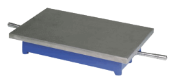
| Surface Plate | An accurately machined flat surface usually made from Cast Iron for stability (larger versions may be called a Surface Table). Work may be placed on here and heights measured from the surface for example.
Note: For most applications in Design and Technology a piece of Float Glass, as used in good quality mirrors for example, would provide an adequately flat reference surface. |
 |
| Scribing Block | A device for holding a Scriber to mark lines at a given height for the datum surface | 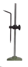 |
| Surface Gauge | Similar to a Scribing Block but with the addition of a fine adjustment screw and sometimes a direct measurement read-out (then known as a Height Gauge) | 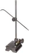 |
| Vee Blocks and Clamp | Used to hold round bar in position on the Surface Plate to enable it to be marked on.
Note: When longer bars need to be supported on two Vee Blocks only a single Clamp is used to ensure they stay flat on the Surface Plate and don't rock. |
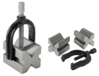 |
| Angle Plate | Used to fix work at right-angles to a Surface Plate or at an angle to it (also used to bolt work to for machining operations) | 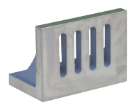 |
| Dial Test Indicator (DTI) | Used to check that a component is parallel to the Surface Plate or flat or to check a bar is round by rotating it on Vee Blocks whilst a DTI is held against it. | 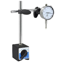 |
| Height Gauges | Similar to Surface Gauges but differ in that they include a scale or read-out to provide measurement directly. They are used in conjunction with a Surface Plate accurately to measure heights from a common datum (i.e. the underside of the cast iron base). | 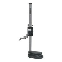 |
| Feeler Gauges | These are thin strips of metal ground very accurately to thickness. They are used to measure small gaps (e.g. spark plug gaps) or clearances between two parts. Imperial measuremnets are in thousandths of an inch (‘Thous’) and metric gauges in hundredths of a millimetre. | 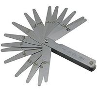 |
| Wire Gauges | Used quickly to measure the diameter of thin wires (e.g. guitar strings) - or the thickness of metal sheets. Wire and sheet is now measured in millimetres and Wire Gauges reflect this, but traditionally, they were used to measure in Standard Wire Gauge (SWG). This has now been superseded but wire gauges are available with dual scales. | 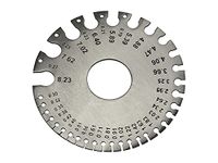 |
| Screw Pitch Gauges | Used as a means of measuring quickly the coarseness (or fineness) of a given screwthread. For Imperial threads this is usually given as the number of threads per inch and, for metric threads, the measurement of the actual thread pitch is provided. Such information is needed when matching screwthreads and, more particuarly, when cutting a screwthread on a Centre Lathe. | 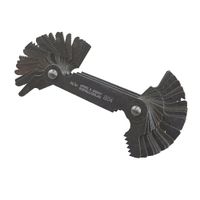 |


