Development of Transition Pieces: Difference between revisions
From DT Online
Created article |
mNo edit summary |
||
| (2 intermediate revisions by the same user not shown) | |||
| Line 1: | Line 1: | ||
[[File:TransitionPieces.png| | [[File:TransitionPieces.png|300px|right]] | ||
__TOC__ | __TOC__ | ||
| Line 5: | Line 5: | ||
=====Description===== | =====Description===== | ||
'''Transition Pieces''' are usually made to connect two different shaped objects ''(e.g. round pipes to square pipes)'' as often found in [https://en.wikipedia.org/wiki/Duct_(flow)#Take-offs '''Ducting'''] for [https://en.wikipedia.org/wiki/Air_conditioning '''Air Conditioning'''] or [https://en.wikipedia.org/wiki/Dust_collection_system '''Dust'''] and [https://en.wikipedia.org/wiki/Exhaust_hood '''Fume Extraction'''] systems. The '''[[Nets and Developments|Development]]''' is constructed by assuming the surface to be made from a series of triangular surfaces laid side-by-side. This technique is known as [https://en.wikipedia.org/wiki/Triangulation '''Triangulation'''] | '''Transition Pieces''' are usually made to connect two different shaped objects ''(e.g. round pipes to square pipes)'' as often found in [https://en.wikipedia.org/wiki/Duct_(flow)#Take-offs '''Ducting'''] for [https://en.wikipedia.org/wiki/Air_conditioning '''Air Conditioning'''] or [https://en.wikipedia.org/wiki/Dust_collection_system '''Dust'''] and [https://en.wikipedia.org/wiki/Exhaust_hood '''Fume Extraction'''] systems. The '''[[Nets and Developments|Development]]''' is constructed by assuming the surface to be made from a series of triangular surfaces laid side-by-side. This technique is known commonly as [https://en.wikipedia.org/wiki/Triangulation '''Triangulation'''] and more specifically as [https://en.wikipedia.org/wiki/Trilateration '''Trilateration''']. | ||
. | . | ||
| Line 16: | Line 16: | ||
* Draw '''Plan''' and '''Elevation''' of the required '''Transition Piece''', | * Draw '''Plan''' and '''Elevation''' of the required '''Transition Piece''', | ||
* Divide the circle into, say, 12 equal points ''(<span style="color: green">Note : in this case, the distances in '''Plan View''' between these points and the sides of the square are all '''True Views'''</span>)'' | * Divide the circle into, say, 12 equal points ''(<span style="color: green">Note : in this case, the distances in '''Plan View''' around the circle between these points; and the lengths of the sides of the square are all '''True Views''' because neither the circle nor the square are tilted in any way - i.e they both lie in the horizontal plane</span>)''. | ||
* Join the corners of the square to the relevant points around the circle ''(<span style="color: green">Note : none of these are '''True Views''' because they are angled either away from or towards you</span>)'', | * Join the corners of the square to the relevant points around the circle ''(<span style="color: green">Note : none of these are '''True Views''' because they are angled either away from or towards you</span>)'', | ||
* Number all points carefully, | * Number all points carefully, | ||
| Line 30: | Line 30: | ||
<div style="clear: both;"></div> | <div style="clear: both;"></div> | ||
=====General Method of Construction for Transition Pieces===== | =====General Method of Construction for Transition Pieces===== | ||
A similar procedure can be used to determine the '''[[Nets and Developments|Developments]]''' for other '''Transition Pieces''' ''(e.g. '''Rectangular to Round, Octagon or Hexagon''')''; for those where the two main axes are offset; and for situations where one pipe is set at an angle to the other. | |||
* Draw '''Plan''' and '''Elevation''' of the required '''Transition Piece''' | * Draw '''Plan''' and '''Elevation''' of the required '''Transition Piece''' | ||
Latest revision as of 07:44, 19 August 2017

Description
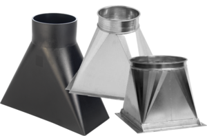
Transition Pieces are usually made to connect two different shaped objects (e.g. round pipes to square pipes) as often found in Ducting for Air Conditioning or Dust and Fume Extraction systems. The Development is constructed by assuming the surface to be made from a series of triangular surfaces laid side-by-side. This technique is known commonly as Triangulation and more specifically as Trilateration. .
Construction for a Square to Round Transition Piece


Consider the example of a Square to Round Transition Piece with both Axes directly in line with each other.
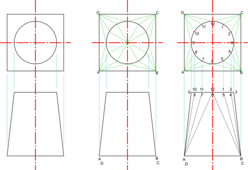
- Draw Plan and Elevation of the required Transition Piece,
- Divide the circle into, say, 12 equal points (Note : in this case, the distances in Plan View around the circle between these points; and the lengths of the sides of the square are all True Views because neither the circle nor the square are tilted in any way - i.e they both lie in the horizontal plane).
- Join the corners of the square to the relevant points around the circle (Note : none of these are True Views because they are angled either away from or towards you),
- Number all points carefully,
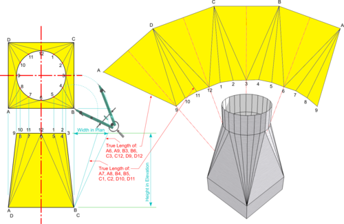
- Use Dividers to transfer the lengths of the joining lines on to a horizontal line as shown (Note : in this case there are only two lines different in length),
- Using the Transition Piece elevation as height and the joining line lengths in Plan as base, draw the hypotenuse to find True Lengths,
- Work around the Plan View and use True Lengths to construct triangles as follows:
- Draw a line to the length of side A-D
- Set Compasses to the True Lengths of A-9 and D-9 and strike arcs from each end of A-D to create the Isosceles Triangle A-D-9,
- Similarly strike arcs equal to True Length D-10 and circle division 9-10 to find point 10.
- Repeat the process, paying careful attention to the point numbering, to construct the full Development.
General Method of Construction for Transition Pieces
A similar procedure can be used to determine the Developments for other Transition Pieces (e.g. Rectangular to Round, Octagon or Hexagon); for those where the two main axes are offset; and for situations where one pipe is set at an angle to the other.
- Draw Plan and Elevation of the required Transition Piece
- Identify convenient points around the perimeter of each shape to be joined (e.g. corners of polygons or equidistant points plotted around the circumference of a circle)
- Note which lines are perpendicular to the viewer (and therefore True Views with True Lengths) and which are not (i.e. because they are sloping away from you or towards you).
- If necessary (e.g. if the axis one pipe is set at an angle to the other), construct an Auxiliary View to establish True Lengths around the perimeters of both shapes to be joined.
- Carefully number all lines joining the two shapes together and note any equalities to avoid unnecessary work later.
- Proceed as for the Square to Round example above to find True Lengths of lines joining the two shapes together (i.e. plot their Lengths in Plan against their Heights in Elevation).
- Use the True Lengths to plot by Triangulation all points on the required Development.


