Milling Machine: Difference between revisions
From DT Online
mNo edit summary |
Added Template |
||
| Line 1: | Line 1: | ||
[[File:MillingMachines.jpg| | [[File:MillingMachines.jpg|400px|right]] | ||
__TOC__ | |||
=====Description===== | |||
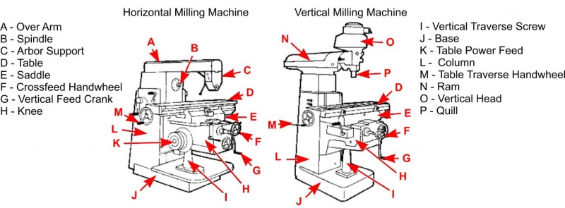
A [http://en.wikipedia.org/wiki/Milling_%28machining%29 '''milling machine'''] is a machine tool used for the shaping of metal and other solid materials. Milling machines exist in two basic forms: [http://en.wikipedia.org/wiki/Milling_%28machining%29#Horizontal_mill '''Horizontal Milling Machines'''] and [http://en.wikipedia.org/wiki/Milling_%28machining%29#Vertical_mill '''Vertical Milling Machines''']. | A [http://en.wikipedia.org/wiki/Milling_%28machining%29 '''milling machine'''] is a machine tool used for the shaping of metal and other solid materials. Milling machines exist in two basic forms: [http://en.wikipedia.org/wiki/Milling_%28machining%29#Horizontal_mill '''Horizontal Milling Machines'''] and [http://en.wikipedia.org/wiki/Milling_%28machining%29#Vertical_mill '''Vertical Milling Machines''']. | ||
=====Features and Applications===== | |||
The direction which the workpiece is fed into the milling cutter determines whether it is a [http://en.wikipedia.org/wiki/Milling_cutter#Conventional_milling_versus_climb_milling '''''‘conventional milling’'''''] operation or [http://en.wikipedia.org/wiki/Milling_cutter#Conventional_milling_versus_climb_milling '''''‘climb milling’''''']. In conventional milling the work is fed in a direction opposite to the tool rotation. The tool starts to cut at the bottom of a revolution and is pushing against the feed. In climb milling the tool starts to cut at the top of each revolution and tends to pull the work through the machine. | The direction which the workpiece is fed into the milling cutter determines whether it is a [http://en.wikipedia.org/wiki/Milling_cutter#Conventional_milling_versus_climb_milling '''''‘conventional milling’'''''] operation or [http://en.wikipedia.org/wiki/Milling_cutter#Conventional_milling_versus_climb_milling '''''‘climb milling’''''']. In conventional milling the work is fed in a direction opposite to the tool rotation. The tool starts to cut at the bottom of a revolution and is pushing against the feed. In climb milling the tool starts to cut at the top of each revolution and tends to pull the work through the machine. | ||
| Line 67: | Line 74: | ||
</span> | </span> | ||
---- | ---- | ||
{{Milling Machine Buyers Guide}} | |||
Revision as of 18:44, 16 August 2016
Description
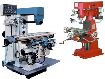
A milling machine is a machine tool used for the shaping of metal and other solid materials. Milling machines exist in two basic forms: Horizontal Milling Machines and Vertical Milling Machines.
Features and Applications
The direction which the workpiece is fed into the milling cutter determines whether it is a ‘conventional milling’ operation or ‘climb milling’. In conventional milling the work is fed in a direction opposite to the tool rotation. The tool starts to cut at the bottom of a revolution and is pushing against the feed. In climb milling the tool starts to cut at the top of each revolution and tends to pull the work through the machine.
Safety Point! Climb milling requires less power and produces a better finish but can lead to serious damage if there is too much ‘backlash’. For this reason climb milling should only be done on manual machines fitted wth backlash eliminators or CNC machines which, by their nature, should be free of any backlash.
With the advent of Computer Numerical Control (CNC), milling machines have evolved into ‘machining centres’ (milling machines with automatic tool changers, tool magazines or carousels, CNC control, coolant systems, and enclosures), and are generally classified as vertical machining centres (VMCs) and horizontal machining centres (HMCs). VMC's are now the most commonly used in schools.
Milling Cutters are available in a wide variety of shapes and range of sizes as shown below. Several can be grouped together along the ‘arbor’ of a horizontal milling machine to accomplish a ‘Gang Milling’ operation in which a whole profile may be machined in a single pass.
| Slab Milling | Also known as Plain Milling, these cutters are designed to remove large amounts of material either for a very wide slot or just to level a surface. They are available in a range of diameters and widths. | 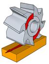 |
| Side and Face Cutter | These cutters have cutting edges round the circumference and also on the sides of the teeth. They can be used for cutting shoulders and slots. They are available in a range of diameters and widths. | 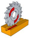
|
| Slitting Saw | This is the basic tool for cutting grooves and slots. They are available in a range of diameters and thicknesses. Slitting saw teeth can have chamfers and radii put on them to cut different shapes. | 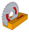
|
| Angle Milling | Single Angle Cutters are used to cut a specified angle, e.g. for a ‘chamfer’ or ‘bevel’, and only cut on one side of the angle. Double Angle Cutters are also available to cut ‘grooves’ with a specific included angle. They cut on both sides of the angle and the teeth of come to point with a small radius on the tip. Similar tasks can be accomplished by use of Chamfer Cutters which are gripped by their ‘shank’ rather than an ‘arbor’. | 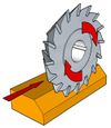
|
| End Milling | Available in a large variety of shapes, styles, and range of diameters, End Mills can side mill, plunge cut and be centre cutting - they can be thought of as the equivalent of router but for cutting metal instead of wood. Rough Cut End Mills are available for rapid metal removal and Slot Drills are used to producing pockets, as a ‘keyway’ for example, without drilling a hole before hand. | 
|
| Face Milling | These are large milling cutters designed for heavy cutting that are meant to remove large amounts of material. They are available in a range of diameters and types of carbide inserts. | 
|
| T-Slot Cutters | These are used to make a pre-cut slot or groove into a ‘Tee Slot’. Machine tables often have Tee Slots in which mounting bolts can be located. | 
|
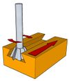
| Milling a Dovetail Slide | Dovetails are shank tools that are used to cut specific angles into the sides of pe-cut slots to create Dovetail Slides - as commonly used on a Lathe Cross-slide for example. The mating half of the slide would be made using an Angle or Chamfer Cutter.
Note: The two parts of a Dovetail Slide are made oversize and packing slips, known as Gib Slips used to produce an accurate sliding fit by adjusting them using a line of lockable screws along the length of the slide. |
|
| Milling a Woodruff Keyway | Typically, these are smaller milling cutters with a shank although they can be in excess of 150mm in diameter. ‘Woodruff Keys’ are small semi-circular shaped pieces of metal which locate in such seatings, leaving a small amount protruding on to which a keyway in a pulley or gear, for example, can be located such that they rotate with the shaft. | 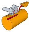
|
Safety Point! Long hair, loose clothing, etc., can become entangled with rotating cutters or arbors and broken cutters, swarf, work pieces, etc., can be violently ejected. Fingers can become trapped under power feed or body crushing can occur between the moving table and a fixed structure.
