Modelling Pulleys
From DT Online
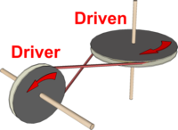
Pulleys a provide a basic method of transferring motion from a motor to a model.
The Pulleys can be made using discs of card and MDF or from 'found objects' such as plastics lids, cotton reels - or even large beads.
Note: If plastics lids or cotton reels are used, card por MDF discs may have to be glued to them using Double-Sided Tape, an Adhesive such as epoxy resin or a Glue Gun since PVA will be ineffective.
Elastic bands provide suitable Drive Belts : for most purposes, use narrow ones and double them up or use several of them if a stronger belt is needed. Wide drive belts will tend to 'climb' out of the Pulley.
Making Pulleys
| Card and MDF Discs | Medium thickness card discs can be glued to each side of an MDF or Ply disc, approximately 10mm smaller in diameter, to make a grooved pulley.
In most cases PVA is a suitable glue to use (i.e. unless the card is laminated or plastics-coated in some way). |
 |
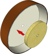
| Screwtop Jar Lids | Typically found as coffee jar lids, these have a deep enough rim not to need any sides to stop the drive belt coming off.
Note: The lids are usually manufactured by a process known as Injection Moulding] and the centre can be found by looking for the small 'pip' left over from where the molten plastics was squeezed in to the mould. |
 |
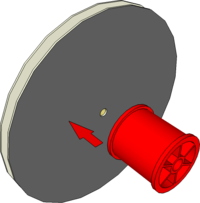
| Cotton Reels | The hole down the centre of cotton reeels will most likely be too big to be a tight fit on Stripwood axles and so they too may need a small MDF or Ply disc gluing on to them (most will be made of plastics so see note about gluing plastics above).
|
 |
| Wooden Beads | The rounded surface of a large wooden bead can simulate the barrel-shaped pulleys once used when a single Lineshaft transferred the power from a central engine to all the machines on a factory floor.
|
 |
Driver and Driven
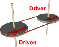
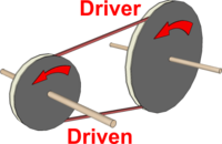
| Same Size Pulleys | If two pulleys of the same diameter are fixed to two parallel shafts then the two shafts will both rotate at the same speed and in the same direction.
|
 |
| Different Size Pulleys | If the two pulleys are different sizes then a smaller Driver pulley will cause a larger Driven pulley to rotate more slowly and a larger Driver pulley will cause a smaller Driven pulley to rotate more quickly.
Activity: What would happen to the speed of a 50mm Driven pulley if the Driver pulley was 100mm diameter? |
 |
Changing Speed
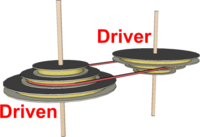
| Cone Pulley | Several grooved pulleys of different diameters can be glued together in a stack as shown. Two such arrangements fixed to parallel shafts, with one upside down to the other, create a Cone Pulley drive as used in many Machine Tools.
|
 |
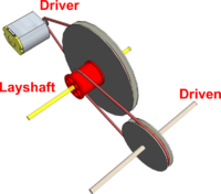
| Double Reduction | An extra axle, known as a Layshaft can be inserted between the Driver pulley and the Driven. A loose fitting double pulley (e.g. made from a cotton reel glued to a larger grooved pulley) is allowed to rotate freely on the Layshaft.
|
 |
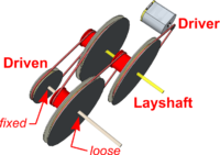
| Multiple Reductions | The idea of using a loose fitting double pulley to enable a second speed reduction can be repeated - several times if necessary. The drive from the motor is then repeatedly transferred from small pulley to large pulley until it reaches the final Driven output pulley.
Note: Although Gears are used instead of Pulleys, the use of a Layshaft in this way is the idea around which car gearboxes are designed. |
 |

