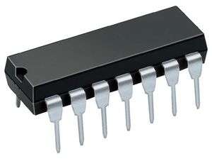
4001 Quad 2 input NOR Gate
From DT Online

Description

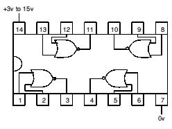
This chip contains four (QUAD) NOR gates, each with 2 inputs, which can operate individually or in combination.
Features and Applications
Uses:
NOR logic gate. Found on electronic resource boards - Short Time Delay 1, Flip Flop 1, Set Reset Flip Flop, Motor Speed Control
In normal use:
Pin 14 (+3 to 15v) is connected to the positive (+ve) supply. Pin 7 is connected to the negative (-ve) supply. All unused inputs should be connected to the positive supply.
Note: The output signal is low powered and normally needs amplification to drive output devices.
Each logic gate works as shown in the truth table.
| Input 1 (eg pin 1) | Input 2 (eg pin 2) | Output (eg pin 3) |
|---|---|---|
| 0 | 0 | 1 |
| 0 | 1 | 0 |
| 1 | 0 | 0 |
| 1 | 1 | 0 |
Connecting two inputs of a gate together (eg 1 & 2) makes the gate act like a NOT gate or INVERTER.


