Calculating Forces in Beams
From DT Online


Equilibrium
When a beam is simply supported at each end, all the downward forces are balanced by equal and opposite upward forces and the beam is said to be held in Equilibrium (i.e. the total load exerted by the beam's own weight plus any additional applied load are completely balanced by the sum of the two reactions at the two supports).
- Place a length of timber, say 1 metre long, between two sets of kitchen scales as shown.
- Adjust the scales until they both read zero - this will take away the weight of the timber itself.
- Place a 2kg mass directly above each of the scales in turn and note the readings - it should be 2kg each time
- Now place the 2kg mass exactly in the centre of the beam and note the readings - they should each be 1kg because the load has been equally shared between the two supports.
What do you think the reading on each would be if you place the 2kg mass just a quarter of the way along the beam (i.e. say, 250mm from one end)?
Try it and see!

Imagine a builder's plank resting on two pieces of scaffolding as shown The loads acting on a beam can be represented in a diagram as a single force acting on the centre of the beam - 'F'
This total downward force must be resisted by upward forces which together are equal and opposite to it. In the diagram these are shown as Reactions R1 and R2
Moments of a Force

If either of the two reactions were to be removed, the beam can be imagined to pivot on the one remaining. It follows that each Reaction must be providing a turning force or Torque to keep the beam in position.
And we know from using a simple lever that it is not just the size of the force or effort that matters but also its distance from the pivot or fulcrum - longer levers need less effort.
The force (created by the load or the effort) multiplied by its distance from the pivot (or fulcrum) is known as the Moment of Force
Torque and Moments are not quite the same thing but both are measured in newtons x metres (Nm)
Calculating the forces acting on a beam

In the case of a Second Class Lever as shown.
- Load x distance d1 = Effort x distance (d1 + d2)

The the load in the wheelbarrow shown is trying to push the wheelbarrow down in an anti-clockwise direction whilst the effort is being used to keep it up by pulling in a clockwise direction.
If the wheelbarrow is held steady (i.e. in Equilibrium) then the moment of the effort must be equal to the moment of the load :
Effort x its distance from wheel centre = Load x its distance from the wheel centre.
This general rule is expressed as clockwise moments = anti-clockwise moments (or CM = ACM)

This gives a way of calculating how much force a bridge support (or Reaction) has to provide if the bridge is to stay up - very useful since bridges are usually too big to just try it and see!
The moment of the load on the beam (F) must be balanced by the moment of the Reaction at the support (R2) :
Therefore F x d = R2 x D

It can be seen that this is so if we imagine taking away the Reaction R2.
The missing support must be supplying an anti-clockwise moment of a force for the beam to stay up.

The idea of clockwise moments being balanced by anti-clockwise moments is easily illustrated using a see-saw as an example . . . .
. . . and we know from our experience that a lighter person will have to sit closer to the end of the see-saw to balance a heavier person - or two people.
- So if CM = ACM then F x d = R2 x D
- from our kitchen scales example above 2kg x 0.5m = R2 x 1m
- so R2 = 1m divided by 2kg x 0.5m
- therefore R2 = 1kg - which is what the scales told us (note the units 'm' cancel out to leave 'kg')

But we can't put a real bridge on kitchen scales and sometimes the loading is a bit more complicated.
Being able to calculate the forces acting on a beam by using moments helps us work out reactions at supports when beams (or bridges) have several loads acting upon them.
In this example imagine a beam 12m long with a 60kg load 6m from one end and a 40kg load 9m away from the same end n- i.e. F1=60kg, F2=40kg, d1=6m and d2=9m
We can out how much of the total load is carried at each support as follows:

- CM = ACM
- (F1 x d1) + (F2 x d2) = R2 x Length of beam
- (60kg x 6m) + (40Kg x 9m) = R2 x 12m
- (60kg x 6m) + (40Kg x 9m) / 12m = R2
- 360kgm + 360km / 12m = R2
- 720kgm / 12m = R2
- 60kg = R2 (note the unit 'm' for metres is cancelled out)
- So if R2 = 60kg and the total load is 100kg (60kg + 40kg) then R1 = 40kg
Vectors

The forces in the loaded beam example are not only important with regard to their size (or magnitude) but also their direction
i.e.
F1 is not only 60kg but is also acting downwards
R1 is not only 40kg but is also acting upwards
It is also established that if the beam is to stay in equilibrium then the sum of all the downward forces must equal the sum of all the upward forces.

Forces are known as vector quantities because they not only have magnitude but also direction.
Vectors can be represented by drawing arrows. The length is equal to its magnitude and the arrow points in the direction the force is acting.
The two loads on the beam can be drawn as vertical lines pointing downwards scaled such that their lengths equal F1 and F2.
Similarly the two reactions can be drawn as vertical lines pointing upwards scaled such that their lengths equal R1 and R2.
The total length of the downward pointing line is equal to the sum of all the downward forces and is known as the Resultant.
The total length of the upward pointing line is equal to the sum of all the upward forces and is known as the Equilibrant - because it is the force required to balance the two loads and maintain balance or equilibrium
Bow's Notation

A labelling convention can be used to make it easier to work on more complex structures.
This is known as Bow's Notation and it is applied simply by working around the structure clockwise and labelling the space between each force in capital letters.

So, starting at R1 for example, space A exists until we meet F1 then the space between F1 and F2 becomes B, etc. etc. This is known as a Space Diagram.
All the forces can then be labelled using the letter on either side - F1 becomes AB, F2 becomes BC etc. etc.
We can now work round the beam clockwise to draw a Force Diagram as follows:
Force AB (F1) goes from a down to b and force BC (F2) goes from b down to c then reaction force CD (R1) goes up from point c to d and force DA (R2) continues up to point a.
The direction is known from the Space Diagram and magnitudes are calculated where possible using Moments - R2 was the only force not calculated
The two lines can be merged together to produce a single Force Diagram representing all the forces on the beam and, if drawn to scale, the value of R2 can be measured.
As before, the Resultant 'ac' can be measured downwards and the Equilibrant 'ca' measured upwards (note that small letters are now used to name the vectors in Force Diagrams).
Bending and Deflection

We also know from experience that if we walk along a builder's plank, for example, it will wobble up and down, or deflect, and we know that it is easier to bend a rule when it is held flat rather than on edge.
If the beam is not strong enough it may deflect so much that it breaks!
The Bending Strength of the beam and its Deflection can both be calculated. The results will depend upon its length, cross section and what material it is made from.
Bending Moments

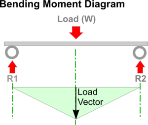
A Bending Moment diagram, as shown, can be drawn by projecting down from the Space Diagram and drawing Vectors to represent the applied loads (i.e. the Load Vector is drawn to a length scaled to represent the magnitude of the Load (W)).
The Bending Moment about either of the Reactions from any point a distance 'x' from them can be expressed as Wx / 2. In the centre of the beam this can be seen to be equal to: Load x Span divided by 4

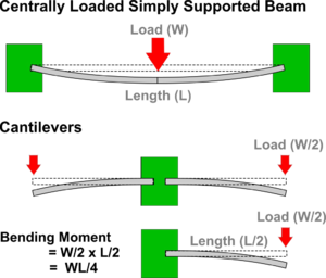
To understand why this is so, imagine the beam to be cut into two then the two halves placed back to back to create two cantilevers each supporting half of the load - and each cantilever will be half the length of the beam of course.
It is clear that standing on the end of a diving board makes it bend the most and this is where to find the Maximum Bending Moment. Moments are given as Force x Distance and in this case, the force is that exerted by the half of the original beam load (W/2) x half the length of the beam (L/2). This can be expressed as Load x Span divided by 4 as shown

Similarly, for a uniformly distributed load (such as the beam's self-weight) the Maximum Bending Moment (BM) is equal to Load x Span divided by 8 (which can also be written as half the load x a quarter of the span)
Self-weight can be assumed to be the same as a single point load acting on the centre of a beam or the cantilever. In the case of this cantilever example, self-weight would be acting therefore a quarter of the way along the beam - or Length = L/4 and the Maximum BM. = W/2 x L/4 = WL/8
For more information on this topic see - 'The New Science of Strong Materials: Or Why You Don't Fall Through the Floor' by J.E.Gordon
Simple Bending Equation


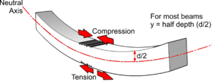
The Maximum Bending Moment may also be calculated using the Simple Bending Equation.
The Simple Bending Equation applies to simply supported beams (and arches if the radius of curvature is greater than 10 times the depth).
Where:
- M = the Maximum Bending Moment
- σ = the Tensile Strength of the material (obtainable from tables or by experiment)
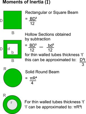
- Capital I = the Moment of Inertia about the Neutral Axis (for a rectangular beam this is its breadth times the depth cubed divided by 12)
- y = the distance of the Neutral Axis from the maximum stress (for a uniform rectangular beam this is half the depth)
Shear Force

The Shearing Force (SF) at any section of a beam represents the tendency for the portion of the beam on one side of the section to slide or shear laterally relative to the other portion.
Starting at the left side of the beam, R1 acts upwards and no other force acts on the beam shown until the centrally applied load W. The Shear Force on the left half of the beam is therefore constant and can be represented on a Shear Force Diagram starting with a Vector drawn upwards to represent R1.
Half way across the beam, the Shear Force then acts downwards because of the load W and is constant along the right half of the beam to R2. Since the beam is in Equilibrium, the Shearing Forces must each start and finish on the same line.
By convention, the Shearing Force on the left of the beam would be rotated clockwise by the combined actions of R1 and W and is therefore labelled positive. The right hand Shearing Force is negative for similar reasons.
Shear Strength is the ability for the material to resist this force.
Beam Deflection
The deflection of a beam under load may be measured using a Dial Gauge for example but may also be calculated.

Deflection (Δ) of a simply supported beam loaded in the centre:
Where:
- W = Load
- L = Span
- E = Young's Modulus
- Capital I = Moment of Inertia ( - a measure of the capacity of a cross section to resist bending)
Cantilevers and Masts

As stated earlier, the Moment of Force is calculated as Load x Distance - for a Cantilever as shown this is WL
From Levers we also know that for this Bending Moment to be maintained then a force applied nearer the support would have to be larger.

The same is true when the cantilever is stood on end - such as when it is a flag pole or a yacht mast.
In the examples of a flag on a flagpole, or a sail on a yacht mast, the force of the wind can be assumed to act through the Centre of Area or Centroid.
For a rectangular flag, this is where the diagonals cross and, for a triangle, it is where each Median intersects.
The magnitude of the Wind Load is less easy to determine but can be derived from tables (obtained by connecting a test flag to a tow line, which is then connected through a load cell to an airplane!)
An estimate of Wind Load adequate for Design and Technology projects with rectangular shaped objects, can be made more easily by disregarding the less critical variables as follows:
Wind Load (N/m2) = ½ x 1.25 (kg/m) x Wind Speed (m/s2) x Area (m2)
Given the Wind Load and the height of the Centroid, the Bending Moment for the flagpole shown is obtained by multiplying them both together.
The Moment of the Force on the flag can be thought of 'levering' against the point of attachment of the guy line at A.
So from Levers, Wind Load x height = F x d
From this, the force at the point of attachment (A) can be calculated and a Force Diagram drawn around point A to determine the tension in the guy line.
