Truss Bridges
From DT Online

Description
Truss bridges are constructed by joining together lengths of material to create a framed structure. The separate lengths of materials are known as frame members and in truss designs, some of these members are in compression and some in tension. Those in compression are known as struts and those in tension are ties.
Features and Uses
All joints between members are assumed to be simply pin joints and are not relied on to provide any rigidity to the structure. Rigidity is ensured by basing the design of the truss frame on triangles.
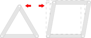
Make a triangle and a rectangle using strips of material - or Meccano for example.
Note that if you apply a force to the side, the rectangle will collapse but the triangle keeps its shape.
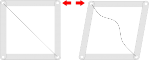
Adding a piece of string across two corners to form a diagonal will stop the rectangle collapsing in one direction but not the other.
This is because the string works well as a tie but cannot be a strut - i.e. you cannot push a piece of string!
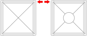
One solution to this problem is to fix two pieces of string and form two diagonals.
This is known as cross-bracing and can be seen in some structures where steel wires are used or metal tie rods are joined together by bolting on to a ring in the centre.
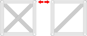
Diagonal bracing and cross bracing are both used in full size bridge structures.
Lattice girders and lattice truss bridges were developed to enable large structures to be built up from a number of lightweight pieces.
The Pratt Truss and Howe Truss are two examples where diagonal bracing has been used to create a rigid bridge structure.
Frame structures which have only just enough members to stay rigid are known as simply firm. A simple test for this is to: double the number of joints then subtract three to find out how many members a frame should have.
From this it can be seen that a triangle (3 joints times 2 less three = 3 members) is 'simply firm' but a square (4 joints times 2 less 3 = 5) is not - it is one member short, or deficient, and this is provided by adding the diagonal.
When two diagonals are added, as in the case of cross-bracing, the square has more members than it should have but this is because it is in effect, two frames one on top of the other - one for loads in one direction and one for the other. For any one loading condition one of the members might as well not be there (like the slackened piece of string) and is known as a redundant member.
This is just a quick and simplified test however and, like many rules, there are exceptions. Whilst a traditional King Post roof truss passes this test for example, the equally traditional Queen Post truss does not!
Warren Truss
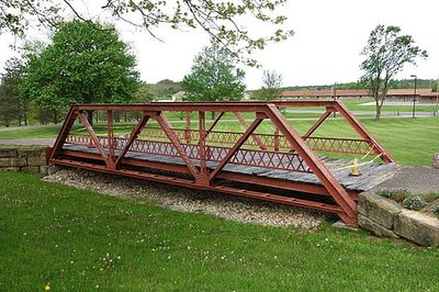
Two British designers, James Warren and Willoughby Theobald Monzani, patented the Warren Truss in 1948
This design of girder is made up entirely of equilateral triangles. As with a simple beam, each member along the top is in compression, a strut, and each along the bottom in tension, a tie. The diagonals can be either struts or ties. When evenly loaded and starting with a strut at each end, the diagonal members alternate between compression and tension towards the centre.
Warren girders are light weight and often used for prefabricated modular bridges such as footbridges because all members are of equal length.
The Warren Girder construction has also been used in aircraft manufacture since the 1920's - e.g. biplanes, some light aircraft and home-build aircraft.
|
Click top left to enlarge |


