Bow's Notation: Difference between revisions
From DT Online
(Created article) |
(Added Template) |
||
| Line 1: | Line 1: | ||
[[File:CloseCoupleBowsNotation.png|300px|right]] | [[File:CloseCoupleBowsNotation.png|300px|right]] | ||
__TOC__ | |||
=====Description===== | |||
'''Bow's Notation''' is a labelling convention whereby the spaces in between any group of forces is labelled with a capital letter such that each force is then straddled by two letters. Since, within a '''[[:Category:Frames|Framed Structure]]''' all forces are assumed to be carried within the frame '''[[Structural Member|Members]]''', it follows that all spaces within a frame are also labelled such that each '''[[Structural Member|Member]]''' is also straddled by two letters as shown. | '''Bow's Notation''' is a labelling convention whereby the spaces in between any group of forces is labelled with a capital letter such that each force is then straddled by two letters. Since, within a '''[[:Category:Frames|Framed Structure]]''' all forces are assumed to be carried within the frame '''[[Structural Member|Members]]''', it follows that all spaces within a frame are also labelled such that each '''[[Structural Member|Member]]''' is also straddled by two letters as shown. | ||
=====Features and Applications===== | |||
Labelling is carried out clockwise around the frame and each joint is then considered in turn, starting with the joint where there is sufficient data to draw a '''[[Force Diagrams|Force Diagram]]'''. | Labelling is carried out clockwise around the frame and each joint is then considered in turn, starting with the joint where there is sufficient data to draw a '''[[Force Diagrams|Force Diagram]]'''. | ||
In | In the example shown: | ||
* we can assume the '''Load''' is known and, working clockwise around the joint at the apex, the '''[[Vector]]''' can be drawn, scaled to its magnitude, and labelled with a direction arrow as creating a force '''a''' down to '''b''' - since we know the load acts downwards ''(note the convention to use lower case letters on '''[[Force Diagrams]]''')''. | * we can assume the '''Load''' is known and, working clockwise around the joint at the apex, the '''[[Vector]]''' can be drawn, scaled to its magnitude, and labelled with a direction arrow as creating a force '''a''' down to '''b''' - since we know the load acts downwards ''(note the convention to use lower case letters on '''[[Force Diagrams]]''')''. | ||
* the '''Lines of Action''' of the force within '''[[Structural Member|Members]]''' '''BD''' and '''DA''' are given by the frame drawing ''(or '''Space Diagram''')'' and can be drawn through '''b''' and '''a''' respectively to intersect in '''d'''. | * the '''Lines of Action''' of the force within '''[[Structural Member|Members]]''' '''BD''' and '''DA''' are given by the frame drawing ''(or '''Space Diagram''')'' and can be drawn through '''b''' and '''a''' respectively to intersect in '''d'''. | ||
| Line 12: | Line 19: | ||
* since all '''[[Structural Member|Members]]''' must stay still, or be in '''[[Equilibrium]]''' there must be equal and opposite forces at the lower ends of '''BD''' and '''DA''' ''(i.e. '''AD''' and '''DB''')'' indicating that the these '''[[Structural Member|Members]]''' are '''[[Strut|Struts]]''' - which is what we would expect. | * since all '''[[Structural Member|Members]]''' must stay still, or be in '''[[Equilibrium]]''' there must be equal and opposite forces at the lower ends of '''BD''' and '''DA''' ''(i.e. '''AD''' and '''DB''')'' indicating that the these '''[[Structural Member|Members]]''' are '''[[Strut|Struts]]''' - which is what we would expect. | ||
* this additional information can be used to determine other forces ''(e.g. the '''Reactions''') by working clockwise around the two lower joints and adding '''dc''' for example, to the '''[[Force Diagrams|Force Diagram]]'''. | * this additional information can be used to determine other forces ''(e.g. the '''Reactions''') by working clockwise around the two lower joints and adding '''dc''' for example, to the '''[[Force Diagrams|Force Diagram]]'''. | ||
{{Construction Kits Buyers Guide}} | |||
[[Category:Terminology]] | [[Category:Terminology]] | ||
Revision as of 19:26, 3 September 2016
Description
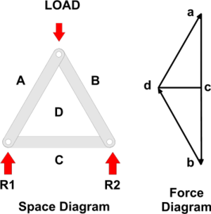
Bow's Notation is a labelling convention whereby the spaces in between any group of forces is labelled with a capital letter such that each force is then straddled by two letters. Since, within a Framed Structure all forces are assumed to be carried within the frame Members, it follows that all spaces within a frame are also labelled such that each Member is also straddled by two letters as shown.
Features and Applications
Labelling is carried out clockwise around the frame and each joint is then considered in turn, starting with the joint where there is sufficient data to draw a Force Diagram.
In the example shown:
- we can assume the Load is known and, working clockwise around the joint at the apex, the Vector can be drawn, scaled to its magnitude, and labelled with a direction arrow as creating a force a down to b - since we know the load acts downwards (note the convention to use lower case letters on Force Diagrams).
- the Lines of Action of the force within Members BD and DA are given by the frame drawing (or Space Diagram) and can be drawn through b and a respectively to intersect in d.
- it is a feature of Force Diagrams that the lines of force will follow each other around a Force Polygon and so, given the downwards direction of ab, it can be seen that, around the apex, the forces within both BD and DA are pointing upwards.
- since all Members must stay still, or be in Equilibrium there must be equal and opposite forces at the lower ends of BD and DA (i.e. AD and DB) indicating that the these Members are Struts - which is what we would expect.
- this additional information can be used to determine other forces (e.g. the Reactions) by working clockwise around the two lower joints and adding dc for example, to the Force Diagram.
|
Click top left to enlarge |


