Force Diagrams: Difference between revisions
From DT Online
Created article |
mNo edit summary |
||
| (6 intermediate revisions by the same user not shown) | |||
| Line 1: | Line 1: | ||
[[File:Haer PBG erection force Diagram s.png|400px|right|Haer PBG erection force Diagram s|link=http://commons.wikimedia.org/wiki/File:Haer_PBG_erection_force_Diagram_s.png]] | |||
__TOC__ | __TOC__ | ||
<big><big>'''Parallelogram, Triangle or Polygon?'''</big></big> | |||
=====Vectors===== | |||
Forces can be represented by lines drawn to scale - known as '''[[Vector|Vectors]]''' provided we know: | Forces can be represented by lines drawn to scale - known as '''[[Vector|Vectors]]''' provided we know: | ||
| Line 15: | Line 19: | ||
Common sense tells us in such a simple example that these two opposing forces could be replaced by a single '''1 [[newton]]'''. force pointing upwards from point '''O''' ''(i.e. the '''[[ | Common sense tells us in such a simple example that these two opposing forces could be replaced by a single '''1 [[newton]]'''. force pointing upwards from point '''O''' ''(i.e. the '''[[Vector|Resultant]]''')'' and the point '''O''' could be held still by a downwards pointing '''1 [[newton]]''' force ''(i.e. the '''[[Vector|Equilibrant]]''')''. | ||
| Line 78: | Line 82: | ||
<div style="clear: both;"></div> | <div style="clear: both;"></div> | ||
=====Calculating Resultants===== | =====Calculating Resultants===== | ||
[[File:TrigCalcs.jpg|400px|left|Trigonometric Ratios]] | [[File:TrigCalcs.jpg|400px|left|Trigonometric Ratios]] | ||
The magnitude of the '''Resultant''' may be measured if drawn to scale but may also be calculated. | The magnitude of the '''Resultant''' may be measured if drawn to scale but may also be calculated. | ||
| Line 88: | Line 90: | ||
For non-right-angled triangles use the '''[[Trigonometry|Sine Rule]]''' ''(hence the magnitudes of forces in a '''Force Polygon''' can be calculated by dividing into triangles)'' | For non-right-angled triangles use the '''[[Trigonometry|Sine Rule]]''' ''(hence the magnitudes of forces in a '''Force Polygon''' can be calculated by dividing into triangles)'' | ||
<div style="clear: both;"></div> | |||
{{Construction Kits Buyers Guide}} | |||
[[Category: | [[Category:Frames]] | ||
[[Category:Terminology]] | [[Category:Terminology]] | ||
Latest revision as of 10:26, 1 March 2017

Parallelogram, Triangle or Polygon?
Vectors
Forces can be represented by lines drawn to scale - known as Vectors provided we know:
- the magnitude
- the point of application
- the line of action
- the direction
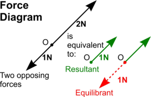
From any point O a line can be draw to a scale representing an upward pointing force of 2 newtons and similarly from the same point, a shorter line to represent the downward pointing force of 1 newton.
Common sense tells us in such a simple example that these two opposing forces could be replaced by a single 1 newton. force pointing upwards from point O (i.e. the Resultant) and the point O could be held still by a downwards pointing 1 newton force (i.e. the Equilibrant).
It is less easy to know the effect of two or more forces acting at a point (i.e. 'concurrent') but are out of line with each other.
Parallelogram of Forces

To find the Resultant (and therefore also the Equilibrant) of two non-aligned forces acting at a point a Parallelogram of Forces can be used.
Vectors are drawn to represent the two forces from any point O as before then lines are drawn parallel to them to complete a parallelogram as shown. The diagonal to this parallelogram is the line of action of the missing resultant or equilibrant and it has been proved that its length is equal to the magnitude.
It is clear from this example that the resultant must be acting upwards and the equilibrant therefore acting downwards if the point O is to remain static.
Triangle of Forces
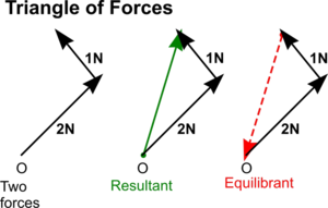
Alternatively, the problem of finding the resultant or equilibrant to two concurrent forces can be found using a Triangle of Forces
In this case, vectors representing the two concurrent forces are drawn to scale end on end as shown. It can be seen that the closing side of the triangle is actually just the same as the diagonal to the parallelogram above and so also provides the line of action and magnitude of the resultant and equilibrant
But it is also a feature of a triangle of forces that the vector direction arrows will follow each other round if the point of application is to remain static. In this way, the triangle of forces gives the direction of the equilibrant - and so the resultant is equal and opposite to it.
Multiple Concurrent Forces
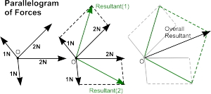
These ideas can be extended when there are more than two concurrent forces.
Several forces can be reduced to a single resultant using Parallelogram of Forces to reduce each pair of them to a single resultant then creating a second parallelogram of force to reduce the two resultants into one.
This process may be repeated as often as is required, depending on the number of concurrent forces in question, until the point is reached when there are just two forces to resolve into one.
Polygon of Forces
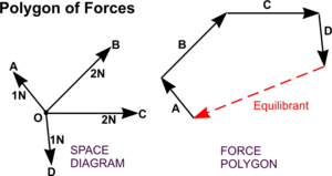
Alternatively, the idea of a Triangle of Forces can be extended to become a Polygon of Forces to solve the problem.
Vectors are drawn end on end, as for the triangle of forces, and the closing side provides the line of action and magnitude of the equilibrant - and the arrows follow round to give the direction.
Bow's Notation
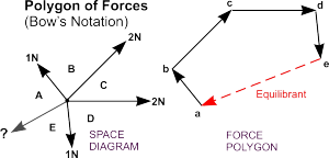
Application of the Polygon of Force can be helped by using Bow's Notation. The position of the missing equilibrant can be estimated then capital letters used to mark each space. Vectors are then drawn as before but labelled ab, bc, etc. - all in lower case letters.
Calculating Resultants
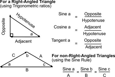
The magnitude of the Resultant may be measured if drawn to scale but may also be calculated.
For right-angled triangles trigonometric ratios (sine, cosine and tangent) can be used.
For non-right-angled triangles use the Sine Rule (hence the magnitudes of forces in a Force Polygon can be calculated by dividing into triangles)
|
Click top left to enlarge |


