Basic Machines: Difference between revisions
From DT Online
No edit summary |
mNo edit summary |
||
| (18 intermediate revisions by the same user not shown) | |||
| Line 1: | Line 1: | ||
[https://en.wikipedia.org/wiki/Machine '''Machines'''] are mechanical devices which are designed such that available sources of energy, force or effort can be used to perform a useful task or to do work. Some Basic Machines simply enable effort to be applied in a more convenient direction, but more often they are used to increase the load that can be moved or amplify the distance travelled. | |||
__TOC__ | |||
=====Description===== | |||
[https://en.wikipedia.org/wiki/Machine '''Machines'''] are mechanical devices which are designed such that available sources of energy, force or effort can be used to perform a useful task or to do [https://en.wikipedia.org/wiki/Work_%28physics%29 '''work''']. | |||
The idea of [https://en.wikipedia.org/wiki/Simple_machine '''Basic Machines'''] was first described by the Greek philosopher [https://en.wikipedia.org/wiki/Archimedes '''Archimedes'''] and further developed by later philosphers. | |||
Some Basic Machines simply enable effort to be applied in a more convenient direction, but more often they are used to increase the load that can be moved or amplify the distance travelled and are therefore [https://en.wikipedia.org/wiki/Mechanical_advantage_device '''Mechanical Advantage Devices'''] | |||
=====Features and Uses===== | |||
{| cellpadding="20" | {| cellpadding="20" | ||
|- | |- | ||
| Line 5: | Line 19: | ||
| [http://wiki.dtonline.org/index.php/Category:Levers '''Levers'''] are described in three ‘classes’ as determined by the relative positions of the '''load''', '''fulcrum''' and '''effort'''. Levers are often used to move heavy loads, as with the Class 1 Lever shown, but if used in reverse, as it were, and the heavy boulder becomes the applied force, then we have the basis of a [https://en.wikipedia.org/wiki/Trebuchet '''Trebuchet'''] type seige weapon making use of the amplification of movement the lever can provide. | | [http://wiki.dtonline.org/index.php/Category:Levers '''Levers'''] are described in three ‘classes’ as determined by the relative positions of the '''load''', '''fulcrum''' and '''effort'''. Levers are often used to move heavy loads, as with the Class 1 Lever shown, but if used in reverse, as it were, and the heavy boulder becomes the applied force, then we have the basis of a [https://en.wikipedia.org/wiki/Trebuchet '''Trebuchet'''] type seige weapon making use of the amplification of movement the lever can provide. | ||
The extent to which a Lever can increase effort is calculated as its '''[[Mechanical Advantage]]''' and the degree to which it amplifies movement is calculated as its '''[[Velocity Ratio]]''' | The extent to which a Lever can increase effort is calculated as its '''[[Mechanical Advantage]]''' and the degree to which it amplifies movement is calculated as its '''[[Velocity Ratio]]''' | ||
| [[File:MechanismsClass1Lever.jpg| | | [[File:MechanismsClass1Lever.jpg|200px]] | ||
|- | |- | ||
| [https://en.wikipedia.org/wiki/Pulley '''Pulley'''] | | [https://en.wikipedia.org/wiki/Pulley '''Pulley'''] | ||
| '''[[ | | '''[[:Category:Pulleys|Pulleys]]''' can be used speed up or slow down rotating shafts or, as in the example shown, simply to change the line of '''effort''' to a more convenient direction. | ||
Whilst a single pulley used as shown conveys no '''[[Mechanical Advantage]]''', multiple pulleys can be used in a [https://en.wikipedia.org/wiki/Block_and_tackle '''Block and Tackle'''] type arrangement to lift heavy '''loads'''. | Whilst a single pulley used as shown conveys no '''[[Mechanical Advantage]]''', multiple pulleys can be used in a [https://en.wikipedia.org/wiki/Block_and_tackle '''Block and Tackle'''] type arrangement to lift heavy '''loads'''. | ||
| [[File:PulleyHoist.jpg| | | [[File:PulleyHoist.jpg|200px|right]] | ||
|- | |- | ||
| [https://en.wikipedia.org/wiki/Pulley '''Windlass'''] | | [https://en.wikipedia.org/wiki/Pulley '''Windlass'''] | ||
| A '''[[Windlass]]''' or [https://en.wikipedia.org/wiki/Wheel_and_axle '''Wheel and Axle'''] is seen wherever there is a winding handle type arrangement. They can be regarded as two different diameter pulleys locked together: the large one, described by the sweep of the handle, being used to apply the '''effort''' and the smaller one, being the diameter of the axle, used to lift the '''load'''. | | A '''[[Windlass|Windlass]]''' or [https://en.wikipedia.org/wiki/Wheel_and_axle '''Wheel and Axle'''] is seen wherever there is a winding handle type arrangement. They can be regarded as two different diameter pulleys locked together: the large one, described by the sweep of the handle, being used to apply the '''effort''' and the smaller one, being the diameter of the axle, used to lift the '''load'''. | ||
All pulleys are essentially levers in rotation and at any moment in time, the windlass can be seen to be a '''[[Class 1 Lever]]''' where the radius of the larger circle described by the handle acts against the smaller radius of the axle. | All pulleys are essentially levers in rotation and at any moment in time, the windlass can be seen to be a '''[[Class 1 Lever]]''' where the radius of the larger circle described by the handle acts against the smaller radius of the axle. | ||
The '''[[Mechanical Advantage]]''' of the Wheel and Axle therefore can be calculated as the diameter swept by the handle divided by the diameter of the axle. | The '''[[Mechanical Advantage]]''' of the Wheel and Axle therefore can be calculated as the diameter swept by the handle divided by the diameter of the axle. | ||
| [[File:MechanismsTheWindlass.jpg| | | [[File:MechanismsTheWindlass.jpg|200px]] | ||
|- | |- | ||
| [https://en.wikipedia.org/wiki/Inclined_plane '''Inclined Plane'''] | | [https://en.wikipedia.org/wiki/Inclined_plane '''Inclined Plane'''] | ||
| Line 24: | Line 38: | ||
The '''[[Mechanical Advantage]]''' of an Inclined Plane can be calculated by dividing its length by its height. | The '''[[Mechanical Advantage]]''' of an Inclined Plane can be calculated by dividing its length by its height. | ||
| [[File:Wedge.jpg| | | [[File:Wedge.jpg|200px]] | ||
|- | |- | ||
| Line 31: | Line 45: | ||
---- | ---- | ||
<span style="color: green">'''Note:''' | <span style="color: green">'''Note:''' | ||
It is for this reason that the long [https://en.wikipedia.org/wiki/Threaded_rod '''studs'''] used to secure an engine cylinder head might have coarse threads into the | It is for this reason that the long [https://en.wikipedia.org/wiki/Threaded_rod '''studs'''] used to secure an engine cylinder head might have coarse threads into the softer aluminium crankcase at the bottom, but finer threads for the steel nut at the top. | ||
</span> | </span> | ||
---- | ---- | ||
The '''[[Mechanical Advantage]]''' of a Screw Thread can be calculated by dividing its pitch by the thread circumference since, for each revolution, a nut advances along the bolt by an amount equal to its pitch : Mechanical Advantage = Distance moved by Effort divided by Distance moved by Load. | The '''[[Mechanical Advantage]]''' of a Screw Thread can be calculated by dividing its pitch by the thread circumference since, for each revolution, a nut advances along the bolt by an amount equal to its pitch : Mechanical Advantage = Distance moved by Effort divided by Distance moved by Load. | ||
| [[File:NutBolt. | | [[File:NutBolt.png|200px]] | ||
|} | |||
=====Animations===== | |||
* Examples from '''[[2100 Animated Mechanical Mechanisms|Nguyen Duc Thang's]]''' YouTube Channel '''[[2100 Animated Mechanical Mechanisms]]'''. | |||
{| | |||
|- | |||
| colspan="5"|[https://youtu.be/oEJqmXyrp8c '''Wedge Mechanism'''] - the height of the mechanism can be regulated by the nut and screw. Cylindrical washers allow the screw change its angle as the Wedges are drawn together. The weight of upper wedge maintains the contact between two wedges.. | |||
| {{#ev:youtube|oEJqmXyrp8c|200x200|right||frame|loop=1&autoplay=0&playlist=oEJqmXyrp8c}} | |||
|- | |- | ||
| [https://youtu.be/TvsxYUj_6wI '''Turnbuckle'''] - the screws have opposite-hand threads. | |||
| {{#ev:youtube|TvsxYUj_6wI|200x200|right||frame|loop=1&autoplay=0&playlist=TvsxYUj_6wI}} | |||
| [https://youtu.be/GrK5bhJjex4 '''Screw Press'''] | |||
| {{#ev:youtube|GrK5bhJjex4|200x200|right||frame|loop=1&autoplay=0&playlist=GrK5bhJjex4}} | |||
| [https://youtu.be/78T8ufcyGjY '''Scissor Jack'''] | |||
| {{#ev:youtube|78T8ufcyGjY|200x200|right||frame|loop=1&autoplay=0&playlist=78T8ufcyGjY}} | |||
|} | |||
{{Basic Machines Buyers Guide}} | |||
[[Category:Primary]] | |||
[[Category:Secondary]] | |||
[[Category:Ancient Greece]] | |||
[[Category:Mechanisms]] | [[Category:Mechanisms]] | ||
Latest revision as of 13:19, 9 October 2017
Description
Machines are mechanical devices which are designed such that available sources of energy, force or effort can be used to perform a useful task or to do work.
The idea of Basic Machines was first described by the Greek philosopher Archimedes and further developed by later philosphers.
Some Basic Machines simply enable effort to be applied in a more convenient direction, but more often they are used to increase the load that can be moved or amplify the distance travelled and are therefore Mechanical Advantage Devices
Features and Uses
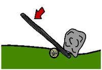
| Lever | Levers are described in three ‘classes’ as determined by the relative positions of the load, fulcrum and effort. Levers are often used to move heavy loads, as with the Class 1 Lever shown, but if used in reverse, as it were, and the heavy boulder becomes the applied force, then we have the basis of a Trebuchet type seige weapon making use of the amplification of movement the lever can provide.
The extent to which a Lever can increase effort is calculated as its Mechanical Advantage and the degree to which it amplifies movement is calculated as its Velocity Ratio |
|
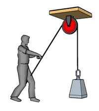
| Pulley | Pulleys can be used speed up or slow down rotating shafts or, as in the example shown, simply to change the line of effort to a more convenient direction.
Whilst a single pulley used as shown conveys no Mechanical Advantage, multiple pulleys can be used in a Block and Tackle type arrangement to lift heavy loads. |
 |
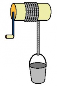
| Windlass | A Windlass or Wheel and Axle is seen wherever there is a winding handle type arrangement. They can be regarded as two different diameter pulleys locked together: the large one, described by the sweep of the handle, being used to apply the effort and the smaller one, being the diameter of the axle, used to lift the load.
All pulleys are essentially levers in rotation and at any moment in time, the windlass can be seen to be a Class 1 Lever where the radius of the larger circle described by the handle acts against the smaller radius of the axle. The Mechanical Advantage of the Wheel and Axle therefore can be calculated as the diameter swept by the handle divided by the diameter of the axle. |
|
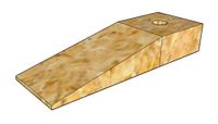
| Inclined Plane | The Inclined Plane in the form of a ramp is used to lift heavy loads but at the expense of having to push them over a greater distance. Two Inclined Planes in the form of a Wedge can be used to grip things tightly or to split (or ‘cleave’) timber for example. Most sharp edge tools, such as chisels, planes and axes, are essentially Inclined Planes and the sharper they are, i.e. the thinner the Wedge, the more easily they cut.
The Mechanical Advantage of an Inclined Plane can be calculated by dividing its length by its height. |
|
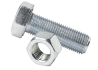
| Screw Thread | A Screw Thread is essentially an Inclined Plane wrapped around a cylinder. Everyday experience suggests that thinner wedges grip more tightly and so it is that fine screw threads are better at resisting vibration and gripping more tightly - but being smaller, they are not as strong and can easily strip when cut into in soft materials.
Note: It is for this reason that the long studs used to secure an engine cylinder head might have coarse threads into the softer aluminium crankcase at the bottom, but finer threads for the steel nut at the top. The Mechanical Advantage of a Screw Thread can be calculated by dividing its pitch by the thread circumference since, for each revolution, a nut advances along the bolt by an amount equal to its pitch : Mechanical Advantage = Distance moved by Effort divided by Distance moved by Load. |
|
Animations
- Examples from Nguyen Duc Thang's YouTube Channel 2100 Animated Mechanical Mechanisms.
| Wedge Mechanism - the height of the mechanism can be regulated by the nut and screw. Cylindrical washers allow the screw change its angle as the Wedges are drawn together. The weight of upper wedge maintains the contact between two wedges.. | |||||
| Turnbuckle - the screws have opposite-hand threads. | Screw Press | Scissor Jack | |||


