Drawing Instruments: Difference between revisions
From DT Online
Removed divders and compassese |
m Changed main image |
||
| (7 intermediate revisions by the same user not shown) | |||
| Line 1: | Line 1: | ||
[[File: | [[File:Architect.png|250px|right]] | ||
Drawing, in its various forms, is the most common way of communicating ideas in '''[[Design and Technology]]'''. Free-hand [https://en.wikipedia.org/wiki/Sketch_%28drawing%29 '''Sketching'''] helps the designer to work out initial ideas and to share them with others. '''Sketches''' can be in '''[[Perspective]]''' or follow one of the more formal [https://en.wikipedia.org/wiki/Technical_drawing '''Technical Drawing'''] conventions such as '''[[Isometric]]''', '''[[Oblique]]''' or '''[[Orthographic]]'''. | __TOC__ | ||
=====Description===== | |||
Drawing, in its various forms, is the most common way of communicating ideas in '''[[Design and Technology]]'''. Free-hand [https://en.wikipedia.org/wiki/Sketch_%28drawing%29 '''Sketching'''] helps the designer to work out initial ideas and to share them with others. '''Sketches''' can be in '''[[:Category:Perspective|Perspective]]''' or follow one of the more formal [https://en.wikipedia.org/wiki/Technical_drawing '''Technical Drawing'''] conventions such as '''[[Isometric Projection|Isometric]]''', '''[[Oblique Projection|Oblique]]''' or '''[[Orthographic Projection|Orthographic]]'''. | |||
| Line 9: | Line 14: | ||
Modern industrial practice has largely replaced the production of '''Technical Drawings''' by [https://en.wikipedia.org/wiki/Drafter '''Draughtsmen'''] working at a drawing board with | Modern industrial practice has largely replaced the production of '''Technical Drawings''' by [https://en.wikipedia.org/wiki/Drafter '''Draughtsmen'''] working at a drawing board with '''[[CAD|Computer Aided Design (CAD)]]''' but this is still based on '''Technical Drawing''' techniques and conventions. | ||
=====Features and Uses===== | |||
{| | {| | ||
|- | |||
| [https://en.wikipedia.org/wiki/Compass_%28drawing_tool%29 '''Compasses'''] | |||
| Used for drawing arcs and circles, these range from simple '''Pencil Compasses''' to the more precise instrument used in [https://en.wikipedia.org/wiki/Technical_drawing '''Technical Drawing''']. As drawing instruments they can have [https://en.wikipedia.org/wiki/Knuckle_joint_%28mechanical%29 '''Knuckle Joints'''] to ensure the pencil lead maintains an [https://en.wikipedia.org/wiki/Angle#Types_of_angles '''Acute Angle'''] to the drawing surface. The leg hinge may be a '''Firm Joint''' with the compasses set and held in position by [https://en.wikipedia.org/wiki/Friction '''Friction'''] or '''Springbow''' compasses have a spring clip holding the hinge together and use a fine screw for adjustment. | |||
| rowspan=3| [[File:Compasses.png|200px|right]] | |||
|- | |||
| '''Beam Compasses''' | |||
| Used for larger diameter circles | |||
|- | |||
| '''Dividers''' | |||
| Used to transfer measurements and similar in all respects to '''Compasses''' but with a [https://en.wikipedia.org/wiki/Stylus '''stylus'''] point on each leg. | |||
|- | |- | ||
| [https://en.wikipedia.org/wiki/T-square '''T-square'''] | | [https://en.wikipedia.org/wiki/T-square '''T-square'''] | ||
| Line 35: | Line 52: | ||
|} | |} | ||
{{Drawing Instruments Buyers Guide}} | |||
[[Category:Marking and Measuring Tools]] | [[Category:Marking and Measuring Tools]] | ||
Latest revision as of 16:48, 9 September 2016
Description
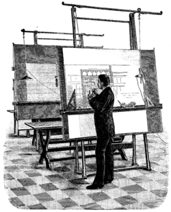
Drawing, in its various forms, is the most common way of communicating ideas in Design and Technology. Free-hand Sketching helps the designer to work out initial ideas and to share them with others. Sketches can be in Perspective or follow one of the more formal Technical Drawing conventions such as Isometric, Oblique or Orthographic.
Sketching is a very quick and free way of working out ideas and all those involved in Design and Technology are encouraged to develop this skill - it only takes practice!
Use of rulers and compasses can help by providing a guide lines for example, but when a design is finalised and a drawing has to be produced which can be measured off, Drawing Instruments are used to create detailed Working Drawings or Plans.
Modern industrial practice has largely replaced the production of Technical Drawings by Draughtsmen working at a drawing board with Computer Aided Design (CAD) but this is still based on Technical Drawing techniques and conventions.
Features and Uses
| Compasses | Used for drawing arcs and circles, these range from simple Pencil Compasses to the more precise instrument used in Technical Drawing. As drawing instruments they can have Knuckle Joints to ensure the pencil lead maintains an Acute Angle to the drawing surface. The leg hinge may be a Firm Joint with the compasses set and held in position by Friction or Springbow compasses have a spring clip holding the hinge together and use a fine screw for adjustment. | 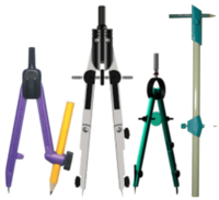 |
| Beam Compasses | Used for larger diameter circles | |
| Dividers | Used to transfer measurements and similar in all respects to Compasses but with a stylus point on each leg. | |
| T-square | A drawing instrument comprising usually a plastics blade and stock made also of plastics or wood which is pressed against the edge of a drawing board to enable parallel lines to be drawn across. |  |
| Set Squares | Triangular shaped Drawing Instruments usually used in conjunction with a T-square or rule to draw lines at 45, 60, 30 and 90 degrees to it. |  |
| Adjustable Set Square | Can be set at any angle to draw a series of parallel lines for example. | 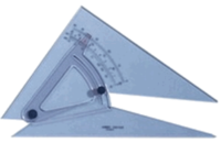 |
| Protractor | Used for measuring angles and available in 180 degree and 360 degree versions | 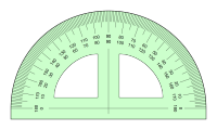 |
| French Curves | A set of templates of curved shapes used for drawing curves through a series of points | 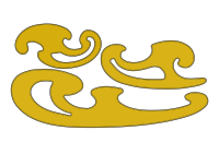 |


