Strength of Materials: Difference between revisions
From DT Online
m Added Category |
m Corrected Link |
||
| Line 208: | Line 208: | ||
Equations for other loading conditions can be found in ''''Structures' by J.E.Gordon ''(ISBN 0 14 02.1961 7)''''' | Equations for other loading conditions can be found in [https://books.google.co.uk/books?id=8p5xgPPJIRYC&redir_esc=y ''''Structures' by J.E.Gordon ''(ISBN 0 14 02.1961 7)'''''] | ||
Revision as of 18:38, 27 December 2015

The strength of structures depends not only on their shape but also on the materials and components from which they are made and the connections between them.
All materials can be described using comparisons such as their strength, durability, appearance and workability. All these material properties can be measured and tested but are also available in tables which can be referred to.
Designers and engineers must know the properties of the materials they use to ensure they will stand up to the intended purpose - otherwise the results can be disastrous!
Stress and Strain
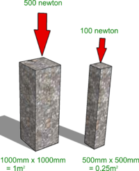
The illustration shows two concrete pillars each with a compressive load applied to the end. It is difficult to know just by looking which of the two pillars is the most likely to break and so engineers need a way doing a fair comparison.
To even things out, engineers calculate how much load would be applied to each square metre of cross-sectional area and this is known as Stress. Many terms in engineering, science and mathematics are represented by Greek symbols and Stress is allocated the symbol σ (sigma).
In the case of the two pillars shown Stress = Load / Area = 500Nm2 for the large pillar and 400Nm2 for the smaller one - so, surprisingly perhaps, it is the large one which might fail first because it is under the greatest Stress.
The pillars would also be squashed a little by the loads upon them - even concrete ones! The amount they are squashed (microscopically small in this case!) is used to calculate the Strain which is equal to the change in length divided by the original length and is allocated the Greek letter ε (epsilon).
Tensile Strength
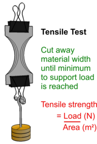
A Tensile Test for thin sheet materials, such as paper, can be done by wrapping the ends of a sample around short pieces of dowel, gripping each end with strong fold-over type paper clips, then loading with a 1kg mass as shown. The sample is progressively reduced in width, taking equal amounts from each side, until it can no longer support the mass. Different types of paper, for example, may be compared for strength - the strongest is the one bearing the 1kg load with least width.
Care must be taken to ensure the material is cut away leaving a smooth edge since any irregularities will create a Stress Concentration and cause the strip to break earlier than expected - try it!
This is a simple Comparative Test. If a numerical result is required the cross-section of the thinned paper strip will need to be measured - ideally in square metres if S.I. Units are to used!
But this can be done - by using a Micrometer for example, and/or measuring the thickness of, say, 100 sheets of paper then dividing by 100, etc..
Stress Concentration
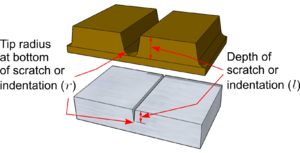
When materials are placed under stress care should be taken to ensure that all edges and surfaces are polished and smooth. Forces will concentrate around even the smallest surface imperfection causing the component to fail sooner than predicted by a theoretical calculation.
This can be catastrophic, as in the case of the Comet airliner disaster, or it can be an intended consequence, as in the case of a bar of chocolate for example.
Calculating the increase in Stress (σmax) is very complex but for a simple scratch or indentation it can be estimated as follows:

Where:
- l = length or depth of scratch
- r = the tip radius at the bottom of the scratch
- Capital I - Moment of Inertia for the material
The key point to note is that the best way to reduce the increase in Stress created by a scratch or cut is to increase the radius at the tip - and that is why drilling a hole at the end of a cut or tear can stop it spreading further!
Tensile Test Rig
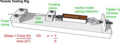
Data from which to calculate the Tensile Strength of stronger materials, can be obtained using the rig shown opposite.
Samples of thin line or wire may be gripped and stretched. As before, the load being applied divided by the cross-sectional area provides a value for the Tensile Stress being applied and any change in length divided by the original length will provide a value for Tensile Strain.
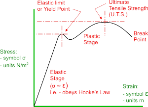
The maximum load the sample can withstand before breaking is known as the Ultimate Tensile Strength (U.T.S.) of the material.
Stress Strain Curve
The rig shown above is known as a Tensometer and industrial devices are used to measure how much a material sample stretches under Stress to determine tensile properties of materials, such as Tensile Strength.
As the material sample is stretched, measurements of the Force applied are taken and divided by the cross-sectional area of the sample to provide the value for Stress. Similarly, the amount the sample stretches is divided by its original length to give a value for Strain.
The values for Stress and Strain can be plotted against each other to produce a curve as shown.
Hooke's Law and Young's Modulus
As material samples are stretched, initially the Stress is directly proportional to the Strain - producing the straight line as shown. The material is behaving in much the same way as a spring would under tension and, if the force is removed, the material returns to its original length. The material is obeying Hooke's Law and this phase is known as the Elastic Stage.
The Stress divided by the Strain during this Elastic Stage is a measure of the stiffness of a material and is known as its Young's Modulus or Modulus of Elasticity.
If a force is continued to be applied beyond this phase, the material reaches a point at which it stays permanently stretched. This is the Yield Point or Elastic Limit and beyond this, during its Plastic Stage, the material will continue to remain permanently deformed until eventually it breaks.
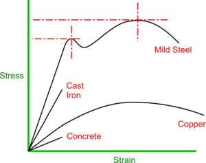
Much can be determined about a material from its Stress/Strain Curve - for example, Ductile materials will exhibit an extended Plastic Stage whereas Brittle materials would have little or none at at all.
In short:
- a stiffer material will exhibit a steeper slope
- a brittle material will lack a plastic region
- a stronger material will show a higher UTS
Compressive Strength
This is a measure of the degree to which a material can withstand being squashed. It can be measured by squeezing a material sample and taking readings in a similar way to Tensile Strength to obtain figures for Compressive Stress and Compressive Strain.
Note that Compressive Strength is not the same as Tensile Strength and the values can be quite different.
As with materials in Tension, materials under Compression will exhibit an elastic stage during which they obey Hooke's Law (e.g. a rubber ball will spring back into shape) and non-brittle material would then exhibit a Plastic Stage (e.g. a ball of wet clay would stay squashed).
But under compression, samples which are too long are more likely to Buckle and very brittle materials may even explode!
Safety Point! Always wear eye protection when testing materials!
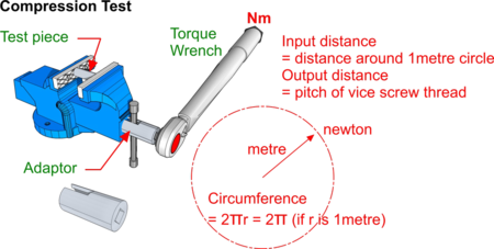
Using a bench vice and Torque Wrench, a compression test can be done as a simple comparison - but the illustration shows how reading a value from the Torque Wrench can even provide a measurement.
The wrench will provide a value in newtons x metres (Nm). If we imagine the wrench to be 1 metre long we can see that, in effect, the reading in Nm is simply the force on the sample (in newtons) x the vice screw thread pitch (in metres) as follows:
Since work in must equal work out (assuming 100% efficiency of the vice of course!) then Force x Distance (in) = Force x Distance (out).
So the Torque Wrench reading (N) x 2πr (in metres) = the vice screw pitch (in metres) x resulting force (in newtons) on the sample. Divide this force by the cross-sectional area (m2) and a value for Compressive Stress can be found.
Trade off
The Young's Modulus is a fundamental property of the material and Heat Treatment processes such as Annealing or Work Hardening - you simply change degrees of Elasticity and Plasticity. The shape of the Stress/Strain Curve therefore changes but the area under it remains the same because the work done to fracture is constant.
Activity:
- Try:
- the tensile testing rig with 1.5mm2 or 18swg samples of copper, aluminium or brass wire;
- the vice compression test rig above with some 20mm long samples of aluminium, copper and brass 8mm or 10mm diameter.
- Test the samples in their original state then anneal and test again to see the difference.
Cross-sectional areas of wire are provided for electrical conductors but may have to be calculated from the diameter for other materials. This can be measured using a micrometer or a Standard Wire Gauge (swg) used and the diameter looked up in tables.
Materials and sections should be chosen so that components are not stressed beyond the Yield Point. In practice, the Working Stress is below this and is determined by the Factor of Safety.
Bending Strength
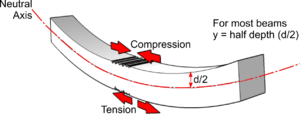
When a beam is loaded and bent as shown, the inside of the bend is subjected to the maximum Compressive Stress and the outside the bend experiences the maximum Tensile Stress.
Since most materials fail under Tension before they fail by Compression, the Bending Strength can be taken to be the same as the Tensile Strength.
Simple Bending Equation
The Simple Bending Equation applies to simply supported beams (and arches if the radius of curvature is greater than 10 times the depth)
This equation can be used to check that a beam has sufficient Bending Strength to support a given load - since it is taken to be the same as Tensile Strength (σ)

Where:
- M = the Maximum Bending Moment
- σ = the Tensile Strength of the material (obtainable from tables or by experiment)
- Capital I = the Moment of Inertia about the Neutral Axis (for a rectangular beam this is its breadth times the depth cubed divided by 12).
- y = the distance of the Neutral Axis from the maximum stress (for a uniform rectangular beam this is half the depth)
Deflection of Centrally Loaded Beams

The equation opposite can be used to find how much a simply supported beam (length - L) would deflect if it is loaded (with a weight W) in the centre. (Note: this equation makes no allowance for self-weight)
Deflection of Beams with a Distributed Load

The deflection equation for a distributed load, such as its self-weight, is given opposite. It can be seen that this is equivalent to multiplying self-weight by 5/8ths then adding it to the centrally applied load in the equation above.
For each of the equations:
- W = Load
- L = length of beam
- E = Young's Modulus for the material used
- Capital I = Moment of Inertia of the beam cross section.
Equations for other loading conditions can be found in 'Structures' by J.E.Gordon (ISBN 0 14 02.1961 7)