Helix: Difference between revisions
From DT Online
Created Helix |
Changed Images |
||
| Line 18: | Line 18: | ||
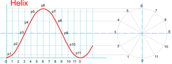
* Continue for all other points then sketch a fair curve through them to create the helix ''(or use [https://en.wikipedia.org/wiki/French_curve '''French Curves'''] or a [https://en.wikipedia.org/wiki/Flat_spline '''flexible strip'''] for example)'' | * Continue for all other points then sketch a fair curve through them to create the helix ''(or use [https://en.wikipedia.org/wiki/French_curve '''French Curves'''] or a [https://en.wikipedia.org/wiki/Flat_spline '''flexible strip'''] for example)'' | ||
</span> | </span> | ||
| [[File: | | [[File:HelixConstruction.png|350px|right]] | ||
|- | |- | ||
| '''Drawing Helical Screws and Springs''' | | '''Drawing Helical Screws and Springs''' | ||
| Line 28: | Line 28: | ||
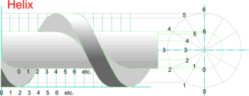
* Careful visualisation and selection of which parts of the helixes are in front and which are hidden will then enable a 3D screw-type form to be completed. | * Careful visualisation and selection of which parts of the helixes are in front and which are hidden will then enable a 3D screw-type form to be completed. | ||
</span> | </span> | ||
| [[File: | | [[File:HelicalScrew.png|350px|right]] | ||
|} | |} | ||
---- | ---- | ||
Revision as of 15:47, 21 February 2015
A Helix is the locus of a point travelling with constant linear velocity, axially along the outside of a cylinder as the cylinder rotates with constant angular velocity. The axial distance travelled by the point for each revolution of the cylinder is known as the pitch.
A helix is the curve used to produce a screw and is common in screwthreads and coil springs.
The elevation of this locus is a Sine Curve, which is also the curve used on a Displacement Diagram to generate Simple Harmonic Motion to a Cam Follower.
| Drawing a Helix |
|
 |
| Drawing Helical Screws and Springs |
|
 |
Note: To draw an actual thread or spring its cross-section must be drawn at the starting point 0 and this used to determine the inner (or ‘core’) diameter, the pitch, and the number of helixes required.