Forces in Frames
From DT Online

The technique of using Force Diagrams to determine missing Reactions comes into its own when considering frames.
When calculating the forces within a frame certain assumptions are made:
- all joints are regarded as pin-joints - like hinges
- all loads and forces are applied at the joints
- forces are carried within the frame members - and so their direction is the force direction
- the frame is in Equilibrium and is statically determinate
Frame Notation

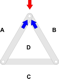
If a simple triangular roof frame is loaded in the same way as a beam, then the Reactions' can be determined in just the same way, but Force Diagrams help us also to find the force in each of the members - and whether they are Struts or Ties.
Bow's Notation can be applied, as when Calculating Forces in Beams, by going around the frame clockwise and labelling each space between forces with a capital letter. The difference is that now the labelling is continued by giving each space within the frame a letter also.
The result is not only that the load is labelled ab and the two reactions bc and ca but the three frame members are labelled AD, BD and CD.
Magnitude of Forces in Frame Members

We can now go around the frame clockwise to draw a Force Diagram .
Starting with the Load force AB, we can draw a Vector scaled to represent its magnitude from a down to b.
Since all forces within the frame must be carried within the frame Members, we can continue to find all the forces around the joint at the top of the frame where the load is applied as follows:
- continuing clockwise round the top joint, force bd must be parallel to member BD and so we can draw a line through b along which d must lie somewhere.
- similarly, force da must be parallel to member DA and can be drawn through a to intersect the force bd at d.
Direction of Forces in Members

It is a feature of drawing Force Diagrams in this way that the arrows follow each other around the force triangle (or polygon)
Continuing to look at the top joint, all the forces, both from the load and within members, are represented in the Force Triangle abd.
We started off by drawing force AB going from a down to b so, following the arrows around the triangle, we now know that, at the top joint, the force in the member BD goes up from b to d and the force in DA goes from d up to a
Struts or Ties?

By Newton's 3rd Law, the force in a member at one end must be balanced by an equal and opposite force at the other.
So, if the member DA is pushing upwards at the top joint, it must be pushing downwards at the bottom (i.e. the member DA is pushing outwards, trying to extend itself, and is therefore a Strut).The same reasoning can be applied to show that BD is also a Strut.
Since points d and c exist on the Force Diagram, then working round the bottom left joint, force dc can be drawn.
Following arrows round the triangle for the bottom left joint ADC, we now know that force ad is downward at that end and so following its direction, cd is pulling inwards - so DC is a Tie which is what we would expect.
Resultants of Forces

Roofs for example, may not only have to carry their own weight, but may also need to withstand the force of wind, or Wind Load for example.
In the example shown, F1 is the force of the wind (or Wind Load) and F2 is the force exerted by the load. By Bow's Notation a letter is allocated to the space between F1 and F2 but we cannot work clockwise around the top joint as before because there are now too many unknowns to complete the Force Diagram
The solution is to reduce the two forces at the top to one - known as the Resultant
A Parallelogram of Forces is drawn in which two adjacent sides are drawn parallel to F1 and F2 and scaled to represent their magnitudes.
The diagonal to this parallelogram is the Resultant - a force which would have the same effect as the other two combined.
Strength of Ties

One purpose of calculating the forces in members is to determine if the size, shape and type of materials they are made from, are sufficient to withstand the loads applied.
The actual load is divided by the cross-sectional area to give the Stress applied as a result.
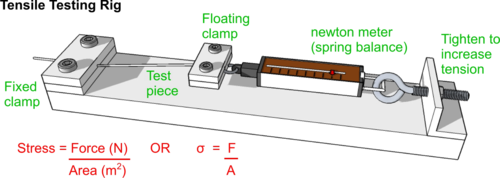
This value can be compared against tables of known values for the Ultimate Tensile Stress of the materials used - or as determined by experiment using a tensile testing rig or Tensometer.
Strength of Struts

These members are subjected to compression and their likelihood to fail simply by lack of compressive strength can be calculated in much the same way as for tensile strength.
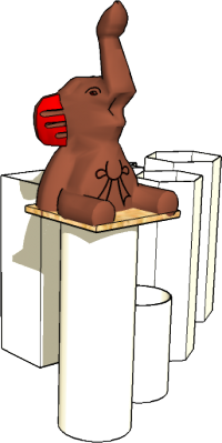
But Struts are more likely to buckle first when subjected to pressure - assuming the struts are made of a sensible material and not something so brittle it is likely to explode under pressure(!)
The point at which a strut might buckle can be assessed using a simplified form of Euler's Buckling Equation as follows:
Where:
- Pcrit = the Critical Force at which the strut will start to buckle
- E = the Young's Modulus of the material (obtainable from tables or by experiment)
- Capital I = the Moment of Inertia about the Neutral Axis (for a rectangular beam this is its breadth times the depth cubed divided by 12)
- L = the length of the Strut (this is taken as the total length since the strut is pin-jointed at each end but would vary with other fixing methods - see Euler's Buckling Equation)
