Cylindrical Cam: Difference between revisions
From DT Online
mNo edit summary |
m (Added Video) |
||
| Line 8: | Line 8: | ||
Properly machined cylindrical cams, as used in engine gearboxes for example, may have slots '''[[Milling Machine|milled]]''' into the side of the cylinder such that the follower is positively driven each way and does not rely on a spring for its return. | Properly machined cylindrical cams, as used in engine gearboxes for example, may have slots '''[[Milling Machine|milled]]''' into the side of the cylinder such that the follower is positively driven each way and does not rely on a spring for its return. | ||
{{#ev:youtube|qYRU5eu1HHI|300|left}} | |||
See '''[[2100 Animated Mechanical Mechanisms|Nguyen Duc Thang's]]''' example of a [https://youtu.be/qYRU5eu1HHI '''Barrel Cam'''] with milled grooves is used in sewing machines to guide thread | See '''[[2100 Animated Mechanical Mechanisms|Nguyen Duc Thang's]]''' example of a [https://youtu.be/qYRU5eu1HHI '''Barrel Cam'''] with milled grooves is used in sewing machines to guide thread ''(right click and select '''Loop''' before starting the video)'' | ||
---- | ---- | ||
<span style="color: green">'''Note:''' | <span style="color: green">'''Note:''' | ||
| Line 17: | Line 17: | ||
</span> | </span> | ||
---- | ---- | ||
[[Category:Secondary]] | [[Category:Secondary]] | ||
[[Category:Cams]] | [[Category:Cams]] | ||
Revision as of 13:13, 9 March 2016
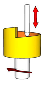
Cylindrical Cams (aka Barrel Cams) are used mainly to convert rotational motion to linear motion parallel to the rotational axis of the cylinder.
A Swashplate may be regarded as a simple form of cylindrical cam.
Properly machined cylindrical cams, as used in engine gearboxes for example, may have slots milled into the side of the cylinder such that the follower is positively driven each way and does not rely on a spring for its return.
See Nguyen Duc Thang's example of a Barrel Cam with milled grooves is used in sewing machines to guide thread (right click and select Loop before starting the video)
Note: They can be modelled by constructing a Displacement Diagram to use as a Template then cutting it out of paper and wrapping it around a tube to show the profile to be cut.
