Four Bar Chain: Difference between revisions
From DT Online
Changed Image |
mNo edit summary |
||
| (3 intermediate revisions by the same user not shown) | |||
| Line 1: | Line 1: | ||
[[File:FourBarChain.png| | [[File:FourBarChain.png|300px|right]] | ||
__TOC__ | |||
=====Description===== | |||
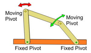
A [http://en.wikipedia.org/wiki/Four-bar_linkage '''Four Bar Chain'''] is a '''[[:Category:Linkages|linkage]]''' with four pivots, two of which are fixed - the bed or surface they are fixed to may be regarded as the fourth bar or link. | A [http://en.wikipedia.org/wiki/Four-bar_linkage '''Four Bar Chain'''] is a '''[[:Category:Linkages|linkage]]''' with four pivots, two of which are fixed - the bed or surface they are fixed to may be regarded as the fourth bar or link. | ||
Varying the lengths of the links can cause the output to speed up or slow down and describe a different arc to the input. The lengths of links can be arranged such that a continuous ''' | |||
=====Features and Uses===== | |||
Varying the lengths of the links can cause the output to speed up or slow down and describe a different arc to the input. The lengths of links can be arranged such that a continuous '''[[Types of Motion|Rotary Motion]]''' input can result in an output with '''[[Types of Motion|Oscillatory Motion]]'''. | |||
Examples of the use of 4 Bar Chains can be found in vehicle [http://en.wikipedia.org/wiki/Double_wishbone_suspension suspension] and [https://en.wikipedia.org/wiki/Ackermann_steering_geometry steering] systems. | Examples of the use of 4 Bar Chains can be found in vehicle [http://en.wikipedia.org/wiki/Double_wishbone_suspension suspension] and [https://en.wikipedia.org/wiki/Ackermann_steering_geometry steering] systems. | ||
=====Animations===== | |||
* Examples from '''[[2100 Animated Mechanical Mechanisms|Nguyen Duc Thang's]]''' YouTube Channel '''[[2100 Animated Mechanical Mechanisms]]''' | |||
{| | |||
|- | |||
| [https://youtu.be/QGKnTEqHSS8 '''Four-bar linkage crane'''] - the end point of the connecting rod draws a straight line. This is used for moving loads in a horizontal direction. | |||
| {{#ev:youtube|QGKnTEqHSS8|200x200|right||frame|loop=1&autoplay=0&playlist=QGKnTEqHSS8}} | |||
| [https://youtu.be/ADofvwxYImA '''Four-bar linkage'''] - the output oscillating angle is larger than 180 deg. which is hard to get by using an ordinary 4-bar linkage. It happens because the sum of the lengths of the two adjacent links is equal to the sum of the lengths of the other two links ''(i.e. pink input crank + con-rod = green output crank + distance between centres)''. The inertia of the green crank must be big enough to overcome the dead position when green crank and yellow con-rod are in line. | |||
| {{#ev:youtube|ADofvwxYImA|200x200|right||frame|loop=1&autoplay=0&playlist=ADofvwxYImA}} | |||
|- | |||
| [https://youtu.be/Aqg7tl4jfe8 '''Four-bar linkage'''] - the green output crank rotates irregularly because the sum of the lengths of the two opposite links is equal to the sum of the lengths of the other two links.''(i.e. input crank + output crank = con-rod length + distance between centres)''. The inertia of the green crank must be big enough to overcome the dead position when green crank and yellow conrod are in line. | |||
| {{#ev:youtube|Aqg7tl4jfe8|200x200|right||frame|loop=1&autoplay=0&playlist=Aqg7tl4jfe8}} | |||
| [https://youtu.be/TAPhhX3ti8s '''Four-bar toggle linkage'''] - the pink crank rotates at constant velocity while orange crank moves slowly at the beginning and end of the stroke. It moves rapidly at the midstroke when the orange crank and the green conrod are in toggle. The accelerated weight on the orange crank absorbs energy and returns it to the system when it slows down. | |||
| {{#ev:youtube|TAPhhX3ti8s|200x200|right||frame|loop=1&autoplay=0&playlist=TAPhhX3ti8s}} | |||
|} | |||
{{Mechanisms Buyers Guide}} | |||
Latest revision as of 13:55, 28 August 2016

Description
A Four Bar Chain is a linkage with four pivots, two of which are fixed - the bed or surface they are fixed to may be regarded as the fourth bar or link.
Features and Uses
Varying the lengths of the links can cause the output to speed up or slow down and describe a different arc to the input. The lengths of links can be arranged such that a continuous Rotary Motion input can result in an output with Oscillatory Motion.
Examples of the use of 4 Bar Chains can be found in vehicle suspension and steering systems.
Animations
- Examples from Nguyen Duc Thang's YouTube Channel 2100 Animated Mechanical Mechanisms
| Four-bar linkage crane - the end point of the connecting rod draws a straight line. This is used for moving loads in a horizontal direction. | Four-bar linkage - the output oscillating angle is larger than 180 deg. which is hard to get by using an ordinary 4-bar linkage. It happens because the sum of the lengths of the two adjacent links is equal to the sum of the lengths of the other two links (i.e. pink input crank + con-rod = green output crank + distance between centres). The inertia of the green crank must be big enough to overcome the dead position when green crank and yellow con-rod are in line. | ||
| Four-bar linkage - the green output crank rotates irregularly because the sum of the lengths of the two opposite links is equal to the sum of the lengths of the other two links.(i.e. input crank + output crank = con-rod length + distance between centres). The inertia of the green crank must be big enough to overcome the dead position when green crank and yellow conrod are in line. | Four-bar toggle linkage - the pink crank rotates at constant velocity while orange crank moves slowly at the beginning and end of the stroke. It moves rapidly at the midstroke when the orange crank and the green conrod are in toggle. The accelerated weight on the orange crank absorbs energy and returns it to the system when it slows down. |


