Crank and Slider: Difference between revisions
From DT Online
mNo edit summary |
m Added links |
||
| (2 intermediate revisions by the same user not shown) | |||
| Line 13: | Line 13: | ||
An air compressor uses this | An air compressor uses this principle in reverse - an electric motor turns the crankshaft and the piston moves up and down to compress the air. | ||
=====Loci===== | |||
It sometimes necessary to know the path traced, or '''[[Loci]]''', of pieces of machinery to check clearances, estimate the velocities at different parts of a linkage ''(perhaps to calculate [https://en.wikipedia.org/wiki/Momentum '''Momentum'''])'' or to design guarding for example. The general method is to draw the linkage or mechanism in several ‘freeze frame’ positions then draw a smooth curve through the plotted points. | |||
{| cellpadding="5" | |||
|- | |||
| '''Plotting Loci on a [[Crank and Slider]] Mechanism''' | |||
| <span style="color:#B00000"> | |||
* Draw a schematic of the '''[[Crank and Slider]]''' and divide the [https://en.wikipedia.org/wiki/Crank_(mechanism) '''Crank'''] rotation into a number of equal divisions ''(say, 12)'' | |||
* Number the [https://en.wikipedia.org/wiki/Crank_(mechanism) '''Crank'''] positions and, with radius set to the length of the connecting rod, strike arcs from each position along the horizontal line which the [https://en.wikipedia.org/wiki/Piston '''Piston'''] is constrained to slide along. | |||
* If the requirement is for the '''Locus''' of the centre of the [https://en.wikipedia.org/wiki/Connecting_rod '''Connecting Rod'''], then mark these points on each position and join with a smooth curve as shown. | |||
* It may sometimes be necessary to draw in additional details of the mechanisms, to test clearances for example. | |||
* '''Loci''' on parts of other mechanisms can be plotted using a similar process ''(i.e. draw the mechanism in different positions and connect plotted points to create the '''Locus''')''. | |||
</span> | |||
| [[File:LociCrankSlider.png |350px|right]] | |||
[[File:LociPistonCrank2.png|350px|right]] | |||
|} | |||
Latest revision as of 09:14, 14 March 2017

Description
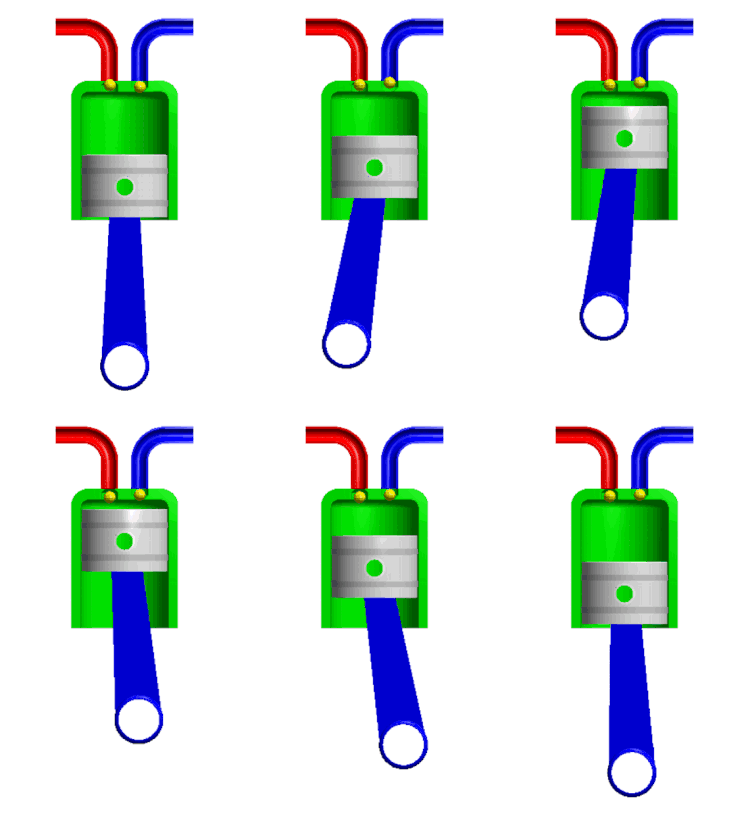
A Crank and Slider mechanism changes rotary to reciprocating motion or vice versa.
Features and Applications
In the car engine the reciprocating motion of the piston caused by exploding fuel is converted into rotary motion as the con-rod moves the crankshaft around.
An air compressor uses this principle in reverse - an electric motor turns the crankshaft and the piston moves up and down to compress the air.
Loci
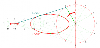
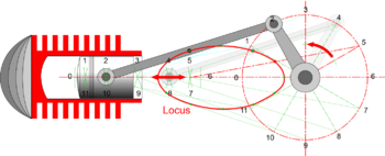
It sometimes necessary to know the path traced, or Loci, of pieces of machinery to check clearances, estimate the velocities at different parts of a linkage (perhaps to calculate Momentum) or to design guarding for example. The general method is to draw the linkage or mechanism in several ‘freeze frame’ positions then draw a smooth curve through the plotted points.
| Plotting Loci on a Crank and Slider Mechanism |
|

 |
Animations
- Examples from Nguyen Duc Thang's YouTube Channel 2100 Animated Mechanical Mechanisms
| Crank and Slider - the piston-rod is extended and works in a guide. The lower part of the connecting-rod is forked to permit the upper part of the piston-rod to pass between. So the piston is guided very well. | Crank and Slider in which the slider reciprocates and turns 90 deg. at the end of its stroke. |


