Sand Casting
From DT Online

(See also Cast Aluminium Plaquette for a simple practical project example)
Description
Sand Casting (aka Green Sand Casting) is a process in which molten metal is poured into a mould cavity made by forming damp (i.e. Green) sand around a Pattern.
The sand used is very finely grained has a clay content (e.g. Bentonite) of around 12% to enable it to retain sufficient moisture such that, when squeezed, it will stick together but not to the hand. A commonly used naturally occuring sand is Mansfield Red Sand. Moulding Sand can be bound with oil instead of mixing with water to make it easier to store and use (i.e. Petrobond).
Simple Patterns may just be one-piece but often need to be split to enable each half to be removed from the mould - more complex Patterns may have additional Loose Pieces which are withdrawn from the mould cavity last of all. Patterns are often made in wood (e.g. Jellutong) and should be made slightly larger than the finished object to allow for contraction. Sides of deeper Patterns are made with a slight taper, Draft or Draw to enable them to be removed from the mould more easily.
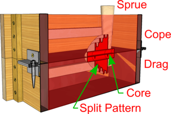
If a hollow form is required, Patterns may include protrusions known as Core Prints, the purpose of which is to create locations in the mould cavity to provide a seating for a Core to create the internal shape.
The sand is packed (or Rammed) around the Pattern inside open ended frames or Moulding Flasks. These are in two parts named Cope and Drag such that they can be separated to remove the pattern and leave a mould cavity.
Runner and Riser Sprues are moulded in and Gates cut to allow the molten metal to flow into the mould cavity and hot gasses to escape.
General Moulding Procedure

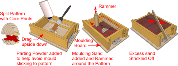
- Patterns are made and, if neccessary split and/or provided with Core Prints - as shown. If a split pattern, location pegs and matching holes are added to ensure correct re-assembly.
- The half of the Pattern without location pegs, is placed on the Moulding Board and the Drag positioned upside down around it.
- Parting Sand (aka Parting Powder - e.g. Talcum Powder) is dusted or sprinkled and brushed over the Pattern to help prevent Moulding Sand sticking to it.
- The Drag is gradually filled with Moulding Sand and packed tight, or Rammed, on to the Pattern using a Rammer, and working round the Drag in circles, starting from the outside and working inwards. Note: good practice is to start with the finest grain Facing Sand nearest the pattern.
- Once filled, the surface of the Drag is levelled off using a flat strip Strickle and turned over to be the right way up.

- The Cope is located on to the Drag and, if a split Pattern is used, the other half added, inserting location pegs into their matching holes. Note: Moulding Flasks also have locating pins which are designed to prevent the two halves being put together the wrong way round.
- Traditionally, two tapered formers known as Sprue Pins are inserted: one is the Runner into which metal will be poured, and the other is the Riser which the metal flows into once the mould cavity is filled.
- Parting Sand added as above to prevent the two halves of the flask sticking together.
- If required, lengths of steel bar can be placed across the top of the Pattern to control which part of the casting will solidify first. These are known as Chills and can help avoid sinking by forcing the extra metal to be drawn from the still molten Runner and Riser as the metal cools and contracts.
- The Cope is Rammed and Strickled as previously and a thin wire (e.g. welding rod) used to create small vent holes down to the Pattern for escaping gasses.
- The two halves of the Moulding Flask are carefully separated and the Pattern withdrawn to leave the mould cavity. This is done by screwing in a Rapping Pin (e.g. a large screw eye) and vibrating it by Rapping from side to side with a metal bar as the Pattern is withdrawn.
- The Sprue Pins are removed and Gates cut from their impressions into the mould cavity through which the molten metal will flow.
- If required, the Core is placed in the Core Prints, any minor damage to the mould cavity is repaired with Moulding Tools and the two halves put back together. Note: long or complex Cores may be supported also by short lengths of metal known as Chaplets set inside the mould cavity.
- Commercially, the surface of the mould cavity may be coated with a wash to help improve the finish on the casting.
- A Runner Cup is prepared by forming sand round the inside of a piece of large metal pipe and placed on top ot the Runner Sprue.
- For safety, the completed Moulding Flask is placed in a sand tray at floor level and the two halves weighted together.
- Metal can now be poured, allowed to cool and the Moulding Flask broken open to reveal the finished casting.
- The Runner and Riser Gates can be cut off with a Hacksaw and the casting fettled with a Millenicut or Dreadnought File.
Safety Point! Pouring molten metal is extremely dangerous!
- Ensure there are no trip hazards between the furnace and the moulding tray containing the flask.
- Make sure that any tools introduced into the melt (e.g. to remove Dross) are pre-heated and dry.
- Wear full face shield, leather gauntlets and apron.
- Use purpose made Crucible Tongs and Carriers to carry the Crucible to the moulding tray and pour.